Are you overwhelmed by the wide variety of lathe cutting tools available on the market? Do you struggle to decide which tool is right for turning, threading, or grooving on your CNC lathe? Choosing the wrong tool can lead to poor machining accuracy, higher costs, tool breakage, and even damaged equipment.
You’re not alone. Many procurement managers and engineers face the same frustration when selecting the right cutting tool. Even experienced machinists may need guidance when dealing with complex materials or advanced tool designs. A single wrong choice doesn’t just waste money on tools—it can cause production delays, increase scrap rates, shorten machine lifespan, and damage customer trust. In today’s competitive manufacturing industry, even small mistakes in tool selection can lead to major losses.
This guide breaks down the essentials of lathe cutting tools—their uses, types, and key selection factors—so you can make informed choices and achieve better machining results.
Why Lathe Cutting Tools Matter
Why lathe cutting tools matter extends beyond tool selection itself. They link machine capability with material behavior, making them central to both process performance and business outcomes.
Accuracy & Efficiency
Lathe cutting tools are one of the key factors influencing machining accuracy. Alongside machine rigidity, workholding, and cutting parameters, the tool’s geometry, material, and coating play a decisive role in chip formation, heat control, and cutting forces. When a tool is properly matched to the workpiece, dimensional accuracy improves, surfaces become smoother, and tolerance levels are easier to maintain.
Well-chosen tools also reduce vibration and chatter, helping operators sustain stability during high-speed CNC turning. This stability translates into shorter cycle times and higher throughput without compromising part quality. In demanding industries such as aerospace and medical devices, where micron-level tolerances are required, the right cutting tool can strongly influence whether a component meets specification or requires costly rework.
Cost & Downtime
Cutting tools are also a major factor influencing the economics of machining. Using an unsuitable grade, geometry, or insert type often accelerates wear, increases the risk of breakage, and raises scrap rates. Each of these outcomes raises the cost per part and forces more frequent tool changes. Downtime during tool changeovers or troubleshooting interrupts production schedules, which is especially damaging in high-volume manufacturing environments.
Selecting a tool that offers stable performance and predictable wear minimizes unplanned stoppages and reduces labor tied to setup and rework. Over time, this improves return on investment by lowering overall tooling costs. In competitive markets such as automotive and energy, even modest gains in tool life or reduced downtime can create meaningful savings across production lines.
Types of Lathe Cutting Tools
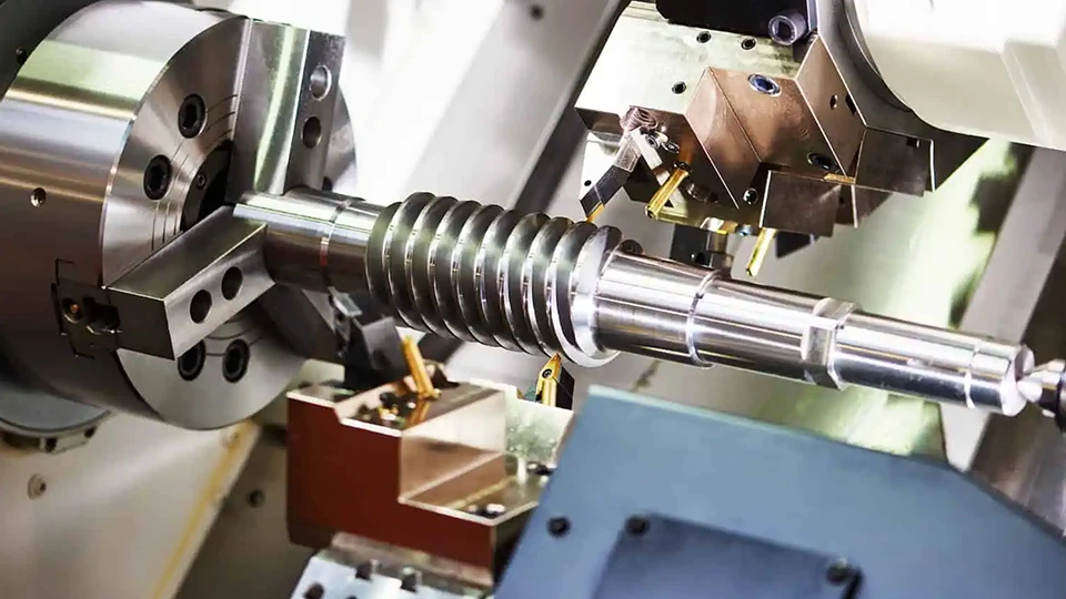
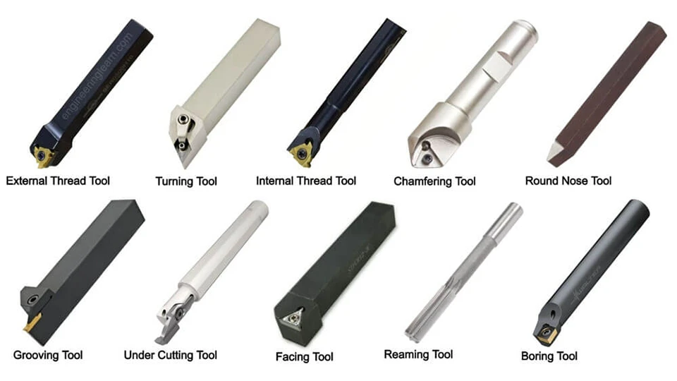
Lathe cutting tools can be grouped in several ways. The most practical approach is to classify them by the type of operation they perform, their structure, feed direction, or geometry.
Based on Operation
Tools differ according to the machining task—whether removing stock, creating threads, parting off material, or shaping features. Below are the main categories of operation-based tools.
Turning tools
External roughing tools
Used for fast stock removal on the outer diameter. These tools often use negative-rake, thick inserts with strong edges and larger nose radii to carry load. Common insert families include CNMG and WNMG in robust toolholders. Typical setup combines higher feed per rev and deeper depth of cut to maximize removal rate, assuming the CNC lathe and workholding are rigid. Flood or high-pressure coolant helps control heat and break chips in long cuts.
External finishing/profiling tools
Designed to hit size and surface finish on the outer diameter and simple profiles. Geometry is usually positive and sharp with smaller nose radii; ground, light-cut chipbreakers are common. VNMG, DNMG, and TNMG inserts are typical choices for profiles and light finishing. Use lower feed and shallow depth of cut to stabilize the cut and protect tolerances. Wiper-edge variants can improve roughness at the same feed.
Facing tools
Applied to square and finish the end face, set datums, and clean up cutoffs. Holders with a near-90° lead angle guide chips away from the center. Surface speed drops near the spindle axis, so reduce feed as you approach the center to avoid tearing. Wiper inserts help achieve a consistent finish across the face. A small center relief or a short dwell-free exit prevents a nub at the very center.
Shoulder/step turning tools
Used to machine sharp 90° shoulders and steps with controlled corner conditions. Choose a holder with the correct approach angle and a small nose radius that fits the required internal corner without rubbing. Program a clean approach and exit path to avoid dwell at the corner. Verify tool overhang and clearance so the holder does not interfere with the shoulder wall.
Copy/contour turning tools
For tapers, blends, and freeform OD profiles. Round (RNMG) and sharp-nose profiling inserts are common because they share load smoothly around curves. Constant surface speed (CSS) helps keep chip load steady along changing diameters. Use stable, moderate feeds and avoid abrupt path changes that can mark the surface. On thin walls, lighter radial engagement reduces distortion.
Radius/fillet turning tools
Used to generate consistent radii and blend features without flats. A form tool with the target radius or a profile insert with a matching nose provides repeatability. Keep feed uniform through the arc to avoid faceting. Verify that the programmed tool nose radius compensation matches the actual edge so the finished fillet size is correct.
Internal turning (boring bars)
Applied to enlarge or finish internal diameters and internal profiles. Bar stiffness is critical: a common rule is steel bars up to 3× diameter overhang and carbide bars up to about 6×; beyond that, consider damped anti-vibration bars. Positive-rake, sharp inserts reduce cutting force in small bores and thin-wall parts. Coolant-through bars improve chip evacuation and temperature control, especially in deep holes. Set the insert orientation for proper clearance on the bore wall, and minimize overhang to control chatter.
Threading tools
External threading tools
Used to cut threads on the outer diameter with single-point inserts on CNC lathes. A short lead-in chamfer helps the tool enter smoothly and reduces burrs. Threading usually runs at lower cutting speeds than general turning to protect the edge and maintain form accuracy. Multiple passes are common, with a light spring pass to stabilize the final flank finish. Select inserts that match the required thread profile (e.g., 60° metric/UN, 55° Whitworth, NPT), and verify with thread gauges before production.
Internal threading tools
Applied inside bores using threading bars with laydown inserts. Pre-bore to the correct minor diameter and add a lead-in chamfer for clean entry. Bar stiffness is critical: minimize overhang to avoid chatter, and use coolant-through bars for deep or blind holes to improve chip evacuation. As with external threading, use multiple passes and a spring pass for flank accuracy. Ensure the bar and insert provide clearance along the helix, and check threads with plug gauges to confirm pitch diameter and form.
Parting & grooving tools
Parting-off blades
Used to cut workpieces to length or separate finished parts from bar stock. Blades are thin to reduce cutting force, but must be rigidly clamped to avoid vibration. A relief or slight taper helps prevent binding in the groove. High-pressure coolant directed into the cut improves chip evacuation and prevents tool breakage.
External grooving tools
Applied to cut grooves, undercuts, or snap-ring seats on the outer diameter. Tool width is chosen to match groove dimensions, and inserts with chipbreaker geometry help control chip flow. Accurate positioning is key, as grooves often serve functional or assembly purposes.
Internal grooving tools
Designed for grooves inside bores. Tool reach and rigidity are critical; minimize overhang to reduce chatter. Coolant-through holders are often required to clear chips from deep grooves. Small-diameter internal grooves may need custom-ground tools or specialized inserts to ensure clearance.
Chamfering & form tools
Chamfering tools (OD and ID)
Used to break sharp edges and create consistent chamfers on both outer and inner diameters. A chamfer improves assembly, reduces stress concentration, and removes burrs that could interfere with fit. Tools are often set at a fixed angle, such as 45°, to ensure repeatability.
Corner radius tools
Designed to blend edges with a defined radius instead of a sharp corner. They are applied to reduce stress risers and improve surface durability, especially in parts exposed to fatigue. Radius values must match drawing requirements to ensure functional performance.
Form/profile tools
Applied to cut complex shapes or repetitive contours in a single pass. These tools are ground to match the required form, which improves cycle time but demands rigid setup. They are best suited for medium-to-high production runs where consistency outweighs flexibility.
Knurling tools
Form (push) knurling tools
Used to press a patterned wheel into the workpiece surface to create a textured grip. Common in hand tools, knobs, and fasteners. Requires sufficient machine rigidity to handle the radial load.
Cut knurling tools
Instead of pressing, these tools cut the knurl pattern into the surface, producing cleaner results with less force. Suitable for harder materials or when high-quality pattern definition is required.
Based on Structure
Lathe cutting tools can also be grouped by how the tool is built. The structure determines cost, regrind options, and how inserts are replaced or resharpened. Single-body, indexable, and brazed designs each offer different trade-offs in rigidity, flexibility, and economy.
Single-body (solid) tools
These tools are made from one piece of material, such as high-speed steel or solid carbide. They are simple, rigid, and easy to regrind, making them suitable for general turning operations and small production runs. However, tool life is limited to the whole tool, and once worn, they must be resharpened or replaced entirely.
Clamped/indexable insert tools
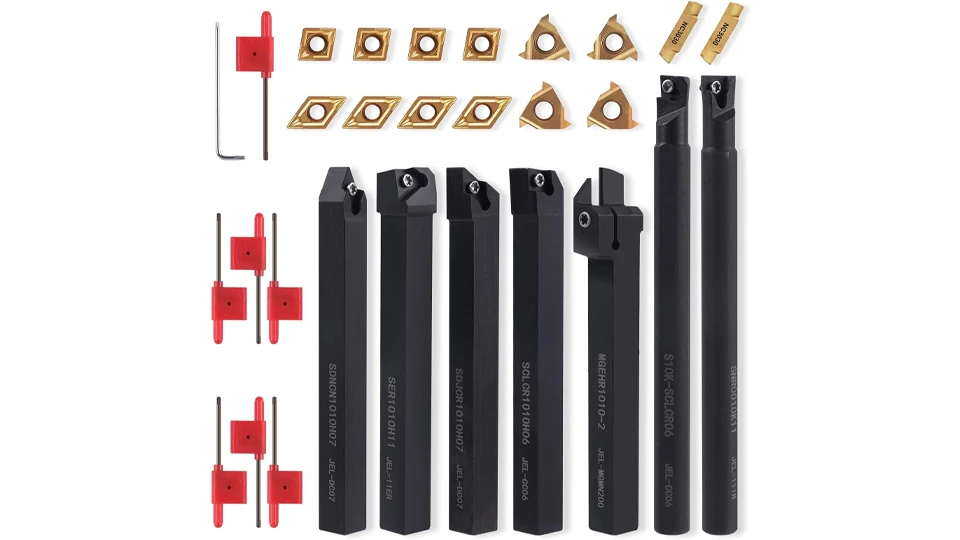
The most common type in modern CNC lathes. A toolholder secures replaceable inserts made from carbide, cermet, ceramic, or other advanced materials. Indexable inserts provide multiple cutting edges, which reduces tooling cost per part and minimizes downtime during changeover. Toolholders come in various geometries to match operations such as roughing, finishing, or profiling.
Brazed carbide-tipped tools
These tools combine a steel shank with a carbide tip brazed at the cutting edge. They are less expensive than solid carbide tools and more rigid than HSS, but once the carbide edge is worn, they require regrinding. They are often used in light-to-medium production or where a cost-effective option is preferred.
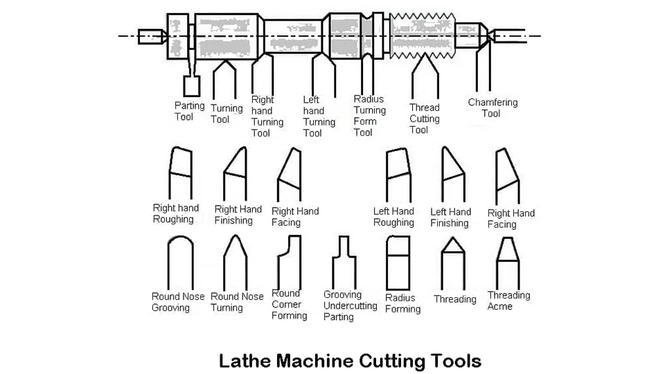
Based on Feed Direction
Feed direction defines how a tool approaches the workpiece—cutting from right to left, left to right, or symmetrically. This classification is critical for setup planning, especially when parts have tight clearance, specific approach angles, or need continuous turning without repositioning.
Right-hand turning tools
Designed to cut when fed from right to left, which is the standard direction on most CNC and manual lathes. These tools remove material as the carriage moves toward the chuck. They are the most common lathe cutting tools and are suitable for general external turning and facing.
Left-hand turning tools
Used when the tool must cut in the opposite direction, feeding from left to right. They are applied for operations where part geometry, machine setup, or clearance makes a right-hand tool impractical. Left-hand tools are often used for back-facing or when machining features close to the tailstock.
Neutral/round-nose tools
These tools can cut in either direction and are often used for light finishing, blending, or when symmetrical toolpaths are required. The round nose distributes cutting forces evenly, which helps achieve smoother finishes on contours and radii. However, they are less effective for heavy stock removal compared to dedicated right- or left-hand tools.
Based on Tool Geometry & Cutting Conditions
Beyond structure and feed, tools are often classified by geometry and the type of cut they perform. Single-point versus multi-point edges, or roughing versus finishing designs, influence chip control, tolerance capability, and the balance between productivity and surface quality.
Single-point vs multi-point tools
Single-point lathe cutting tools have a single cutting edge in contact with the workpiece. They are used for external turning, facing, boring, and profiling operations. Their strength is versatility and simplicity, making them the foundation of most lathe work. Multi-point tools, such as knurling wheels or threading chasers, engage multiple edges at once. These increase productivity by removing material faster or forming patterns more efficiently, but require higher machine rigidity and generate more heat.
Roughing vs finishing tools
Roughing tools are built for strength and durability. They often feature stronger inserts, larger edge radii, and chipbreakers designed to handle thick chips at higher feeds and depths of cut. The focus is on fast stock removal, not surface finish. Finishing tools, in contrast, have sharper geometries and smaller nose radii to achieve tight tolerances and smooth surfaces. They are applied at lighter feeds and depths of cut, with stable conditions to minimize vibration. The right balance of roughing and finishing passes ensures both efficiency and quality in CNC turning.
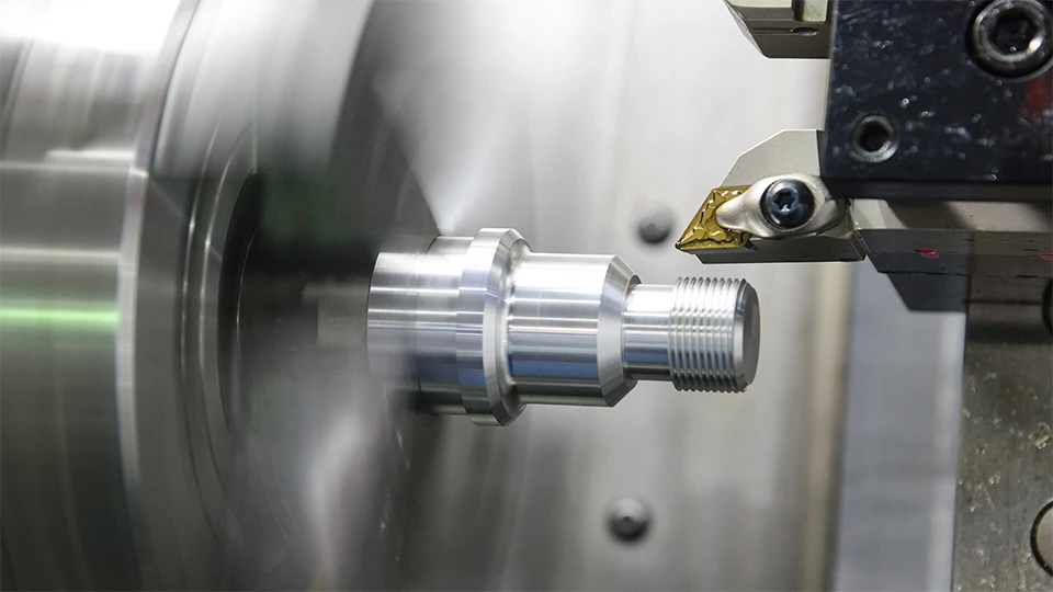
Materials Used in Lathe Cutting Tools
The performance of a lathe cutting tool depends not only on its geometry but also on the material it is made from. Tool material governs cutting speed, wear resistance, toughness, and suitability for different workpiece alloys. Choosing the right tool material is essential for balancing productivity, tool life, and cost in CNC turning.
High-Speed Steel (HSS)
HSS lathe cutting tools are tough and forgiving. They tolerate interrupted cuts, light chatter, and manual setups better than brittle materials. Edges are easy to regrind and shape for specials, which keeps cost low in small batches. Cutting speeds are modest, and hot hardness limits high-temperature work. HSS is a good fit for training, job-shop one-offs, and complex form tools where frequent resharpening is acceptable.
Carbide cutting tools
Carbide combines high hot hardness with good wear resistance, making it the default choice for CNC lathe production. It runs higher surface speeds and supports chipbreakers that stabilize chip flow at practical feeds. CVD or PVD coatings such as TiN, TiCN, TiAlN, or AlTiN further improve edge life and reduce crater wear. Grades are selected by material group and cut mode, from continuous finishing to heavy roughing. Carbide is ideal for steels, cast irons, and many nonferrous alloys where predictable life and lower cost per part matter.
Cobalt-based tools
Cobalt-alloyed HSS (such as M35 or M42) raises red hardness and compressive strength compared with standard HSS. These tools hold an edge longer at higher temperatures and are useful for tougher steels, small interrupted cuts, and applications where carbide is too brittle or too costly to fixture. They still grind easily, so special profiles are practical. Speeds remain below carbide, but tool life is more stable than plain HSS in demanding conditions.
Ceramic and diamond tools
Ceramic inserts excel at high-temperature, high-speed cutting of cast irons and heat-resistant alloys. They prefer stable cuts and rigid setups and are not suited to heavy interruption. Polycrystalline diamond (PCD) tools deliver exceptional finish and very long life in aluminum, copper, and abrasive composites; they should not be used on ferrous steels due to chemical wear. Both categories reward consistent feeds, controlled heat, and accurate toolpaths when chasing ultra-fine surface finish or tight size control on a CNC lathe.
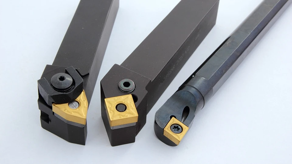
How to Choose the Right Lathe Cutting Tool
Selecting the right lathe cutting tool is about more than just matching insert shape to a drawing. The choice must account for workpiece material, machine capability, production volume, and cost targets. A tool that performs well in one setup may fail in another if these factors are ignored. Understanding how each consideration influences tool performance helps ensure stable processes, consistent quality, and optimized cost per part.
Factors based on workpiece material
Workpiece material is the first filter when selecting lathe cutting tools.
- Steel: General steels are best cut with carbide inserts in ISO P grades, often coated with TiCN, TiAlN, or AlTiN for wear resistance. High-alloy or hardened steels may require tougher grades, edge preps, or even ceramic/cBN tools for finishing.
- Aluminum: Requires sharp, positive-rake tools to avoid built-up edge. Polished uncoated carbide or diamond (PCD) tools provide excellent surface finish. Wide chipbreakers prevent clogging with long, ductile chips.
- Titanium: Needs sharp carbide with strong edge support and heat-resistant coatings. Lower cutting speeds and high-pressure coolant are essential to control heat and prevent notching.
- Composites: Highly abrasive fibers demand PCD or diamond-coated tools. Rake geometry must minimize delamination, while controlled feeds reduce fraying at edges.
Selecting the right tool grade for the workpiece material reduces wear, improves finish, and extends tool life. Ignoring this match often results in rapid tool failure and lost productivity.
Considering machine type
The machine itself places limits on tool choice.
- Manual lathes: Manual lathes typically operate at lower spindle speeds and with less rigidity than CNC machines. High-speed steel tools or brazed carbide-tipped tools are practical because they are tough, inexpensive, and easy to resharpen. They also tolerate the variable feeds and depth of cut common in hand operation.
- CNC lathes: With higher spindle speeds, programmable feeds, and rigid setups, CNC machines benefit from indexable carbide inserts, ceramics, or diamond tools. These materials support high cutting speeds and deliver consistent performance across long production runs. CNC holders also allow precise tool positioning, critical for automated cycles and repeatability.
Matching the cutting tool to the machine’s capability ensures stable performance. Using advanced inserts on an underpowered manual lathe wastes tooling, while limiting a CNC to HSS reduces its potential efficiency.
Production volume: single-part vs mass production
The number of parts to be produced has a direct impact on tool selection.
- Single-part or small batches: Flexibility and low upfront cost are most important. High-speed steel tools or brazed carbide-tipped tools are practical because they can be ground to custom shapes and resharpened when needed. They are cost-effective for prototypes, repairs, and job-shop work where tool life is less critical.
- Mass production: Consistency, tool life, and changeover speed dominate. Indexable carbide inserts or advanced ceramics are preferred because they support higher cutting speeds and predictable wear. Multi-edge inserts reduce downtime and lower cost per part. Automated CNC lathes rely on these tools to maintain stable processes over thousands of cycles.
Adapting tool choice to production scale balances cost with efficiency. Using disposable inserts for a one-off part wastes money, while running HSS in a high-volume line limits productivity.
Balancing cost, durability, and precision requirements
No single lathe cutting tool optimizes every factor. A tool with excellent durability may be too expensive for low-volume jobs, while a low-cost tool may wear out quickly and cause rework. Precision requirements also influence selection: achieving fine tolerances or superior surface finish often demands higher-grade inserts, specialized coatings, or carefully ground geometries.
The best choice depends on the trade-offs. For roughing operations in large batches, a durable indexable carbide insert offers the lowest cost per part. For tight-tolerance finishing in aerospace or medical parts, premium grades or diamond tools may be justified despite higher upfront cost. Evaluating tooling cost alongside expected tool life and quality needs ensures stable machining and predictable return on investment.
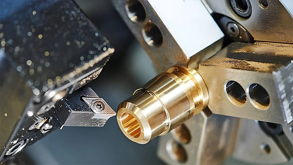
Maintenance and Care for Lathe Cutting Tools
Proper maintenance extends the life of lathe cutting tools and protects machining consistency. Without it, even high-quality tools can wear prematurely, generate poor finishes, or fail unexpectedly. Simple routines for handling, storage, sharpening, and monitoring tool wear help keep both cost and downtime under control.
Proper storage and handling of cutting tools
Store lathe cutting tools in labeled trays or original insert boxes to avoid edge damage and mixing grades. Separate new, used, and scrapped inserts. Keep holders, shims, and screws together as a set with IDs (insert shape, nose radius, grade, edge prep). Clean holders before mounting—remove chips, dried coolant, and tramp oil; check pocket flatness and clamp surfaces. Use a torque driver to tighten insert screws to the manufacturer specification; replace worn screws and clamps. Avoid dropping tools, sliding edges across metal benches, or touching edges to grinding dust. Keep storage dry and clean to prevent corrosion on steel shanks and screws.
Sharpening and regrinding practices
Regrind HSS and cobalt tools on a balanced wheel with coolant to avoid temper loss; use aluminum-oxide wheels for HSS and dress frequently for a cool, sharp cut. Maintain clearance and rake angles consistently, and keep the nose radius uniform across tools. After grinding, lightly hone the edge with a fine stone to remove micro-burrs and stabilize the edge. For brazed carbide, grind with diamond or CBN wheels under coolant; avoid overheating the braze joint. Indexable inserts are not normally reground—rotate to a fresh edge and replace when edges are consumed. Record geometry and edge prep on a simple tool card so regrinds remain consistent between operators.
Lubrication and cooling considerations
Choose coolant type to match the job: emulsions or semi-synthetics for general steel turning, synthetic or high-lubricity fluids for difficult alloys, and MQL or neat oil for aluminum where finish is critical. Aim the nozzle at the shear zone and chipbreaker; consistent delivery improves chip control and edge life. For deep bores and grooves, internal (through-tool) coolant helps evacuate chips and manage heat. Maintain concentration with a refractometer, skim tramp oil, and service filters; contaminated or low-concentration coolant accelerates wear and degrades surface finish. Avoid intermittent coolant on hot ceramic tools to prevent thermal shock.
Monitoring tool wear and replacement schedules
Track wear modes, not just time. Flank wear (VB) grows predictably; notch wear at the depth-of-cut line, crater wear, built-up edge, micro-chipping, or thermal cracking point to mismatched grade, coating, or parameters. Set practical change criteria—e.g., a finishing tool is replaced at a small VB value to protect size and roughness, while a roughing tool runs to a higher VB limit if stability remains acceptable.
Use CNC tool-life counters (parts, time, or cutting length) and, where available, spindle power or load monitors to flag abnormal rises that precede failure. Inspect pulled tools under magnification, log life per edge, and update parameters or grades when wear patterns repeat. Replace clamps, seats, and screws on a schedule; a fresh insert in a worn pocket will not hold tolerance.
Safety Practices When Using Lathe Cutting Tools
Safe use of lathe cutting tools is as important as tool performance itself. Even well-selected and well-maintained tools can cause accidents if installed or handled carelessly. By following structured safety practices, machinists protect both productivity and operator health while extending machine life.
Safe handling and installation of cutting tools
Always inspect tools and holders before mounting. Check inserts for cracks, worn edges, or chipping, and make sure clamping screws are tightened to the manufacturer’s torque specification. Never use makeshift shims or damaged toolholders, as they can release under cutting load. During setup, keep hands clear of the sharp cutting edges and use gloves when carrying or handling tools off the machine.
Operator protection (PPE, guarding, chip control)
Operators should wear safety glasses with side shields, hearing protection where required, and snug-fitting clothing to avoid entanglement. Machine enclosures or guards must remain closed during operation to contain flying chips and coolant spray. Chip control is essential: use chipbreakers, appropriate feed rates, and high-pressure coolant if available to prevent long, stringy chips from wrapping around the part or tool.
Avoiding common mistakes that cause accidents
Several recurring errors lead to unsafe conditions. Overextending boring bars or other long tools increases the chance of vibration and sudden breakage. Running dull tools risks insert fracture, which can eject fragments at high speed. Incorrect spindle speeds, especially starting a cycle with too high an RPM, can also damage the setup. Finally, operators should avoid reaching into the machine while it is running — all adjustments, cleaning, and measurements should be done only after full stop and lockout.
Conclusion
Lathe cutting tools shape the outcome of turning operations more than any other factor. Across roughing, finishing, threading, grooving, chamfering, and boring, tool design and material dictate not only accuracy and surface finish but also production speed and economy. By looking at tool types, tool materials, and the practical criteria for choosing between them, this guide highlighted how decisions made at the toolpost ripple through machining performance, tool life, and shop efficiency. Maintenance and safety practices complete the picture, ensuring that the best tool choice delivers consistent value over time.
Manufacturers that treat tool choice, maintenance, and safety as part of a unified process see the strongest gains in productivity and reliability. The machine itself must support these practices with rigidity, coolant delivery, and stable interfaces for modern tooling systems. This is the focus at Rosnok, where our CNC lathes and machining centers are built to maximize the performance of cutting tools—whether indexable inserts, boring bars, or threading systems—so that shops can translate sound tooling decisions into repeatable results on the shop floor.
