In real machining, chip formation affects much more than chip shape. It influences tool life, surface finish, cutting temperature, machining accuracy, and production efficiency. Poor chip control can cause tool wear, workpiece scratches, unstable cutting, machine downtime, and safety risks. For CNC lathes, milling machines, machining centers, and drilling machines, understanding chip formation helps operators choose better cutting parameters and improve machining results.
This article explains what chip formation is, why it matters, common chip types, key influencing factors, typical problems, and practical ways to improve chip control in CNC machining.
What Is Chip Formation in Machining?
Chip formation is the process in which material is removed from a workpiece and becomes chips during machining. In metal cutting, the tool does not simply “scrape away” extra material. It forces the material to deform, separate, and flow away from the cutting zone as a chip.
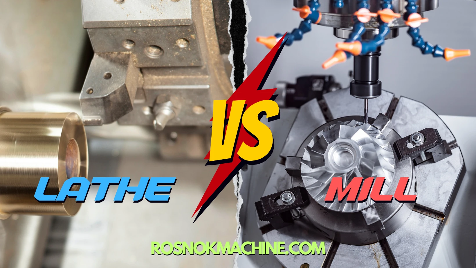
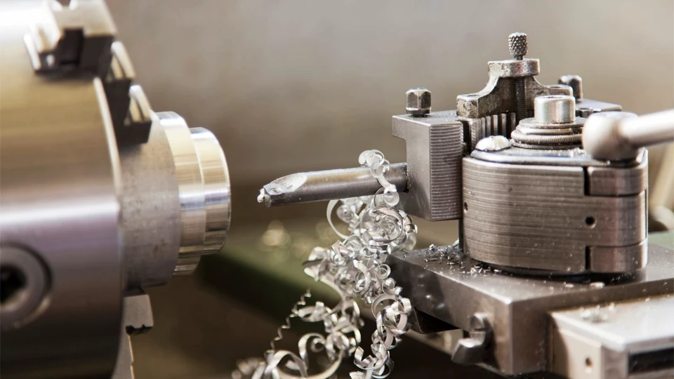
This process happens in almost every machining operation. In turning, chips form as the tool cuts the rotating workpiece. In milling, chips are produced each time the rotating cutter teeth enter and leave the material. In drilling, chips form inside the hole and move along the drill flute. In boring and threading, chip formation also determines how smoothly material is removed from the cutting area.
How Chip Formation Happens During Metal Cutting
Chip formation happens through a controlled cutting action. When the tool meets the workpiece, the material is compressed, deformed, sheared, and guided away from the cutting zone. Understanding this basic process helps explain why chips form differently under different machining conditions.
Cutting, Shearing, and Plastic Deformation
Chip formation begins when the cutting tool enters the workpiece material. The tool edge applies high pressure to a small contact area. Under this pressure, the material ahead of the cutting edge is compressed and starts to deform.
This deformation is not only surface scratching. In metal cutting, the material first undergoes plastic deformation. As the tool continues moving, the deformed material is forced to separate from the workpiece and becomes a chip.
The Role of the Shear Zone
The key area in chip formation is the shear zone. This is the narrow region where the material is heavily deformed before it separates from the workpiece. When the cutting stress becomes higher than the material can resist, the material shears along this zone.
The shear zone explains why chip formation is a controlled cutting process, not random breaking. The material fails in a specific direction under the action of the tool, cutting force, and workpiece resistance.
How Chips Flow Along the Cutting Tool
After separation, the chip moves along the rake face of the cutting tool. During this movement, friction and heat are produced between the chip and the tool surface. Cutting force also continues to act on the chip as it curls or flows away from the cutting area.
Tool geometry affects this flow. The rake angle, edge shape, and chip groove can change the chip direction and curling behavior. Workpiece material also matters. Ductile materials usually deform more before separation, while harder or more brittle materials tend to separate with less plastic deformation.
Why Chip Formation Matters in CNC Machining
Chip formation matters because it shows whether the cutting process is stable, controlled, and safe. In CNC machining, chips are not only removed material. They are also visible evidence of how well the tool, workpiece, cutting parameters, heat, and machine movement are working together.
Chip Formation as a Signal of Cutting Stability
Stable chip formation usually means the cutting process is running in a predictable way. The tool is removing material smoothly, the cutting force is relatively controlled, and the chip can leave the cutting area without disturbing the workpiece or tool path.
When chip formation becomes unstable, the machining process may also become unstable. Chips may come out unevenly, change color, break irregularly, or remain near the cutting zone. These signs can suggest excessive heat, poor cutting balance, tool wear, weak clamping, or vibration.
For CNC machining, this matters because the machine often runs continuously according to a programmed path. If chip formation is poor, the problem may continue through many parts before the operator notices a dimensional error, surface defect, or tool failure.
Why Poor Chip Control Creates Real Production Problems
Poor chip control can affect production in several direct ways. Chips may scratch the machined surface, block the cutting area, wrap around the tool, or interfere with coolant flow. In automatic machining, long or uncontrolled chips can also create safety risks and increase downtime.
Chip formation also connects to cost. If chips are not controlled well, the tool may wear faster, cutting temperature may rise, and the machine may need more frequent stops for cleaning or inspection. This reduces production efficiency and increases maintenance pressure.
For this reason, chip formation is not a small detail in CNC machining. It is one of the easiest process signals to observe, and it often gives early warning before larger machining problems appear.
Main Types of Chips in Machining
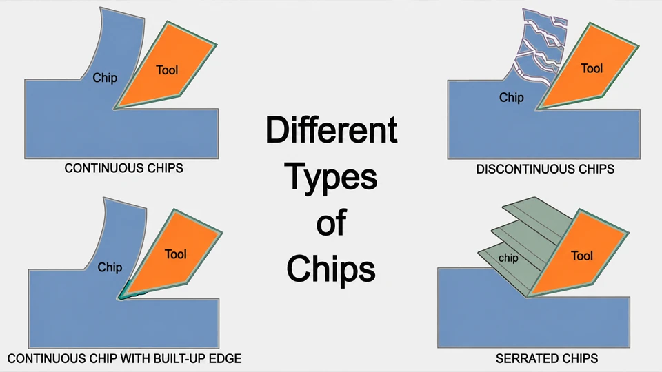
Different machining conditions create different chip shapes. These chip shapes are not random. They are influenced by material behavior, cutting stability, tool condition, and heat in the cutting zone. Understanding the main types of chips helps identify what kind of cutting behavior is taking place.
Continuous Chips
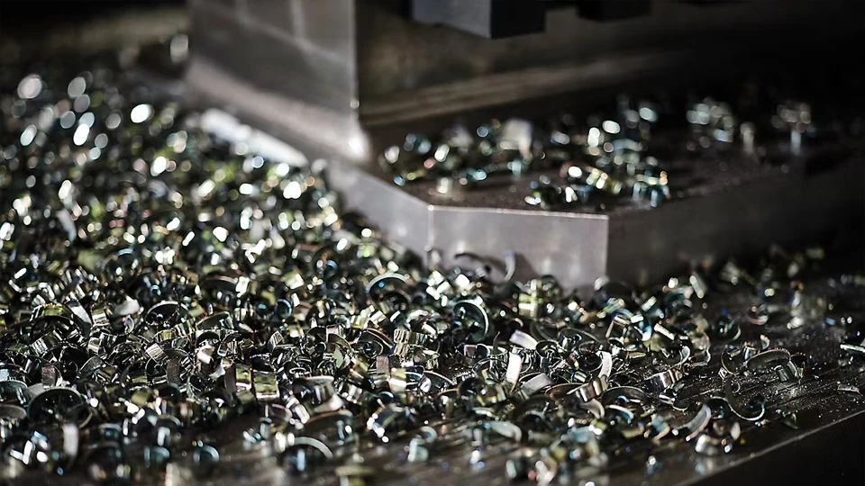
Continuous chips are long, smooth chips that form without frequent breaking. They are common when machining ductile materials, especially when the cutting tool is sharp and the cutting action is stable.
This type of chip often indicates smooth material flow and relatively steady cutting force. However, continuous chips are not always ideal. If they become too long, they may wrap around the tool, workpiece, or fixture. In CNC machining, this can affect safety, chip evacuation, and automatic production stability.
Discontinuous Chips
Discontinuous chips are short, broken chips that separate into small segments. They often appear when machining brittle materials, such as cast iron, or when cutting conditions are not fully stable.
These chips are usually easier to remove from the cutting area. However, if discontinuous chips are caused by vibration, excessive tool wear, or unsuitable cutting conditions, they may also indicate rough cutting behavior. In that case, the machined surface may become less consistent.
Built-Up Edge Chips
Built-up edge chips occur when part of the workpiece material sticks near the cutting edge of the tool. This attached material temporarily changes the real cutting edge and affects how the chip separates from the workpiece.
This condition is more likely when machining sticky or ductile materials, especially under low-speed cutting or insufficient lubrication. Built-up edge can make the cutting process unstable and may affect dimensional accuracy and surface quality.
Serrated Chips
Serrated chips have a saw-tooth shape along the chip edge or surface. They are often seen when machining difficult materials, such as titanium alloys, stainless steel, and high-temperature alloys.
This chip type is related to repeated shearing during cutting. The material does not flow evenly. Instead, it deforms and separates in a more segmented pattern. Serrated chips can appear in high-speed or high-temperature cutting conditions, especially when the material has low thermal conductivity or strong resistance to deformation.
Key Factors That Affect Chip Formation
Chip formation changes when the cutting conditions change. The main factors are workpiece material, cutting speed, feed rate, depth of cut, tool geometry, coolant, and machine rigidity. Each factor affects how the material deforms, separates, curls, and leaves the cutting zone.
Workpiece Material
Workpiece material is one of the first factors that determines chip formation. Ductile materials, such as aluminum alloy and low-carbon steel, usually deform more before separation. They are more likely to form longer chips.
Brittle materials, such as cast iron, tend to break more easily during cutting. Stainless steel, titanium alloy, and high-temperature alloys often generate more heat and cutting resistance, so their chip formation can be less stable and harder to control.
Cutting Speed
Cutting speed affects cutting temperature, material softening, and chip flow. A higher cutting speed usually increases heat in the cutting zone and may make the material easier to shear. In some cases, this helps the chip flow more smoothly.
However, cutting speed must match the material and tool. If the speed is not suitable, chip formation may become unstable, and heat may build up near the tool edge.
Feed Rate
Feed rate affects chip thickness. A higher feed rate usually produces a thicker chip and increases cutting force. A lower feed rate produces a thinner chip, but the chip may become harder to break in some materials.
Feed rate also changes how strongly the tool engages with the workpiece. If the feed is too unstable, chip thickness can vary, and the cutting process may become less consistent.
Depth of Cut
Depth of cut controls how much material is removed in one pass. A larger depth of cut produces a wider or heavier chip and increases the load on the tool and machine. A smaller depth of cut reduces cutting load, but it may also change chip thickness and chip shape.
In practical machining, depth of cut must stay within the capacity of the tool, workpiece setup, and machine structure.
Tool Geometry
Tool geometry directly guides how chips form and move. Rake angle affects how easily the material flows over the tool. Edge radius affects how the tool presses and separates the material. Nose radius affects cutting contact and surface generation.
Chip grooves and chip breakers are also important because they shape the chip after it forms. They can change chip curling behavior and help make chip flow more predictable.
Coolant and Lubrication
Coolant and lubrication affect chip formation by reducing heat and friction. Better cooling helps control cutting temperature. Better lubrication helps the chip move along the tool surface with less sticking.
This is especially important when machining sticky materials or when chips must leave a narrow cutting area. Without proper coolant or lubrication, chips may stick, overheat, or flow poorly.
Machine Rigidity
Machine rigidity affects whether the tool can cut steadily under load. If the spindle, tool holder, fixture, or machine structure is not rigid enough, vibration may occur. Once vibration appears, chip thickness and chip flow can become unstable.
Good rigidity helps keep the cutting edge in a stable position. It also supports more consistent chip formation, especially during heavier cutting or precision CNC machining.
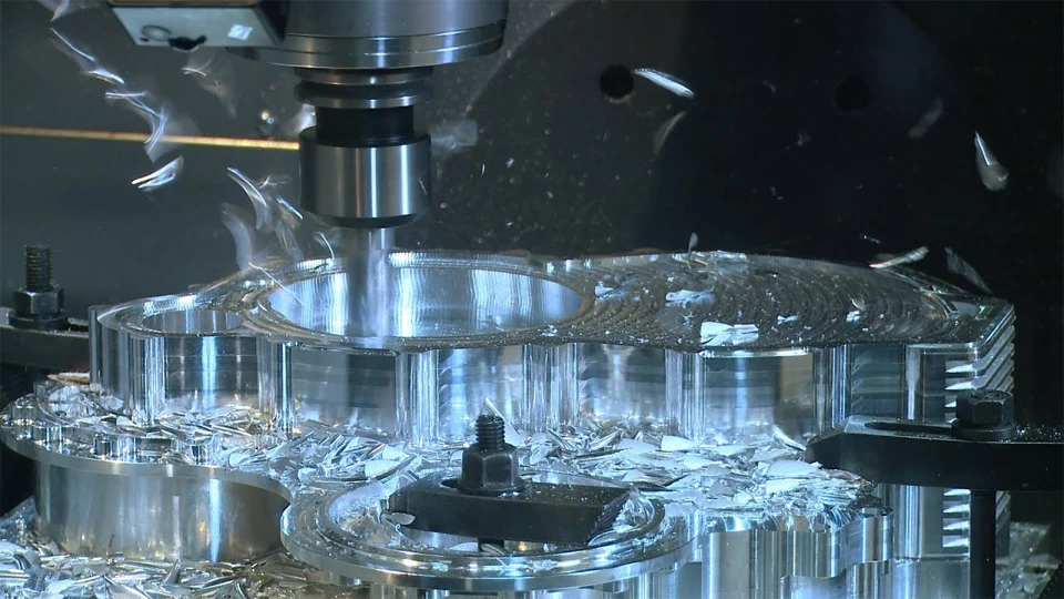
Chip Formation in Different Machining Processes
Chip formation appears in many machining processes, but it does not happen in exactly the same way. The motion between the tool and the workpiece changes how chips are created, shaped, and removed from the cutting area.
Chip Formation in Turning
In turning, the workpiece rotates while the cutting tool moves along the workpiece surface. Because the cutting contact is usually continuous, the chip often flows steadily from the cutting edge.
This is why long chips are common in turning, especially when machining ductile metals. On CNC lathes, pipe threading lathes, and vertical lathes, chip direction and chip breaking are important because uncontrolled chips may wrap around the tool, chuck, workpiece, or fixture.
Chip Formation in Milling
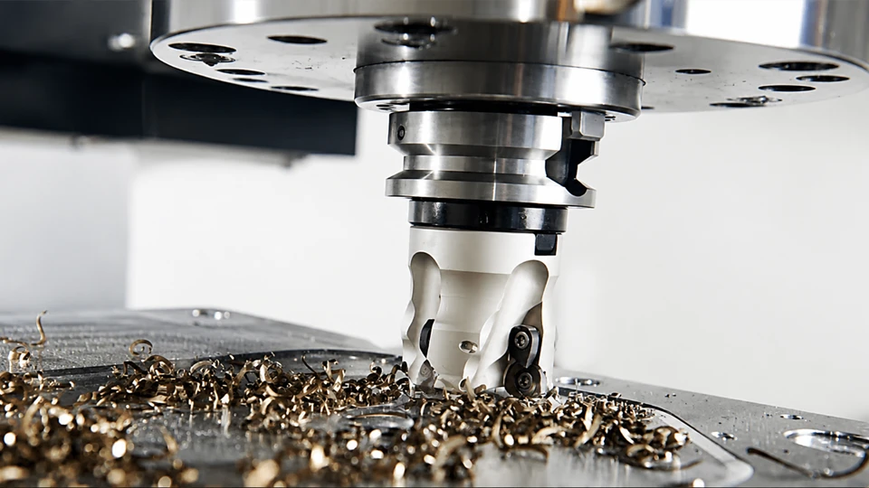
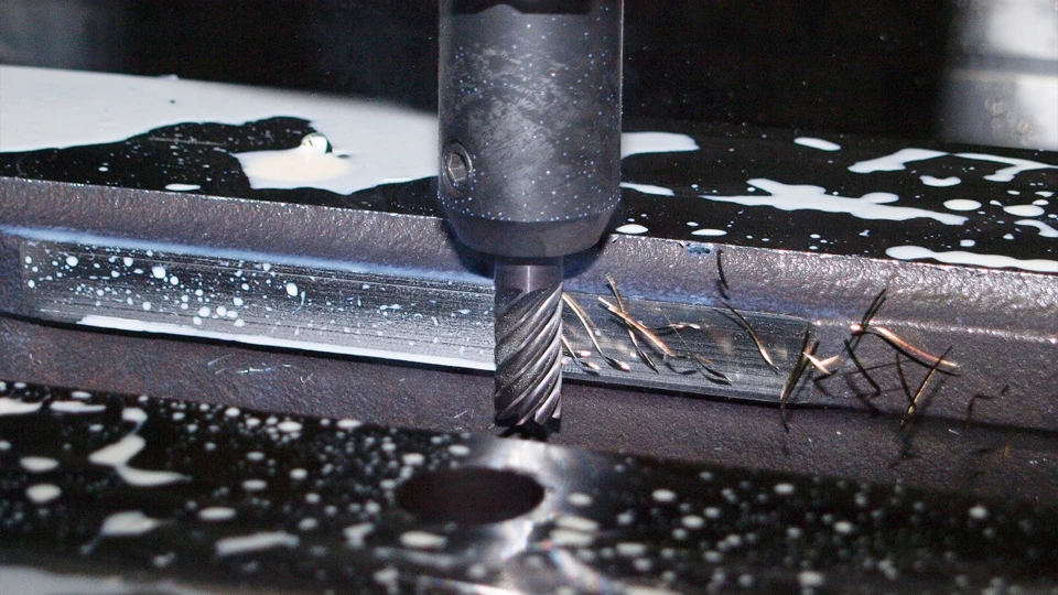
In milling, the cutting tool rotates, and each cutting edge enters and leaves the workpiece repeatedly. This makes chip formation more intermittent than turning.
Each tooth removes a small amount of material during its cutting pass. Feed per tooth, number of cutting edges, cutting width, and tool engagement all affect chip thickness. Because the cutting action is interrupted, milling is also more sensitive to impact, vibration, and tool-workpiece stability.
Chip Formation in Drilling
In drilling, chips form inside the hole and must move out through the drill flutes. This makes chip evacuation more difficult than in open cutting operations.
If chips cannot leave the hole smoothly, they may block the flute, increase cutting temperature, damage the hole wall, or even break the drill. In deep-hole drilling, chip evacuation becomes even more critical because chips have a longer path to escape.
Chip Formation in Threading
In threading, the cutting tool forms a precise thread profile while removing material from the workpiece. Chip control is important because chips can interfere with the thread form and damage the finished surface.
For pipe threading, chip formation is especially important because thread quality affects connection accuracy and sealing performance. Poor chip evacuation may scratch the thread, disturb the profile, or reduce the consistency of the final threaded surface.
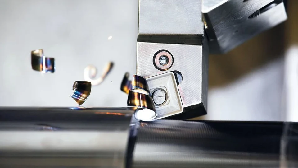
Common Chip Formation Problems and What They Mean
Chip formation problems are often early signs of an unstable cutting condition. They do not always point to one single cause, but they help operators narrow down where to check first: material behavior, tool condition, cutting parameters, coolant, or machine stability.
Long Stringy Chips
Long stringy chips usually appear when machining ductile materials. They may also happen when the chip breaker is not suitable, the feed rate is too low, or the cutting condition does not support effective chip breaking.
The main risk is chip wrapping. Long chips can wrap around the tool, workpiece, chuck, or fixture. They may scratch the machined surface, interrupt automatic production, block coolant flow, and create safety risks for operators.
Powdery or Broken Chips
Powdery or heavily broken chips are common when machining brittle materials, such as cast iron. However, if they appear unexpectedly, they may indicate tool wear, cutting impact, vibration, or unstable parameters.
These chips are usually easy to remove, but they can also signal rough cutting behavior. The possible risks include poor surface quality, tool edge damage, and fine particles entering sensitive machine areas.
Blue or Burnt Chips
Blue or burnt chips often suggest excessive cutting temperature. This may come from high cutting speed, insufficient coolant, heavy tool wear, or too much friction at the cutting edge.
The risk is not limited to chip color. Excessive heat can shorten tool life, affect dimensional stability, increase thermal deformation, and cause surface damage on the workpiece.
Chips Sticking to the Tool
When chips or workpiece material stick to the cutting edge, it may indicate built-up edge, strong material adhesion, poor lubrication, or an unsuitable tool coating.
This problem changes the real cutting edge during machining. As a result, the part size may become unstable, the machined surface may become rougher, and the tool edge may wear or chip faster.
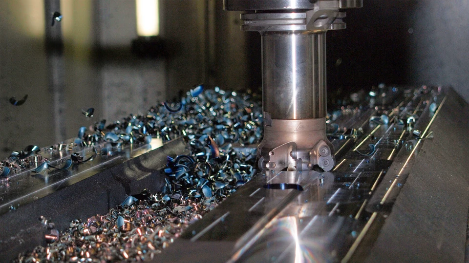
How Chip Formation Affects Tool Life and Surface Finish
Chip formation directly affects tool life and surface finish because the chip stays in contact with the cutting edge during material removal. If the chip forms and leaves the cutting zone smoothly, cutting is more stable. If it flows poorly, sticks, overheats, or breaks irregularly, both the tool and the finished surface can suffer.
Impact on Tool Life
Poor chip formation increases the load on the cutting edge. When chips do not flow smoothly, friction rises between the chip and the tool surface. This creates more heat near the cutting edge and accelerates tool wear.
Unstable chips can also hit or drag across the tool edge. This may cause edge chipping, crater wear, flank wear, or faster coating damage. Built-up edge is another problem because attached material changes the real cutting edge and makes cutting less predictable.
Stable chip formation helps distribute cutting force more evenly. The tool still wears during machining, but the wear process becomes more controlled. This gives operators a better chance to maintain tool life, part accuracy, and production consistency.
Impact on Surface Finish
Chip formation also affects the final machined surface. If chips flow in the wrong direction, they may rub against or scratch the newly cut surface. If cutting becomes unstable, vibration marks or uneven texture may appear.
Built-up edge can make the surface worse because the tool is no longer cutting with a clean edge. Instead, material may be torn, pressed, or smeared across the surface. Excessive cutting heat can also damage surface integrity and make the finish less consistent.
When chip formation is stable, the cutting edge removes material more smoothly. This helps produce a more uniform surface texture and more reliable surface roughness, especially in precision CNC machining.
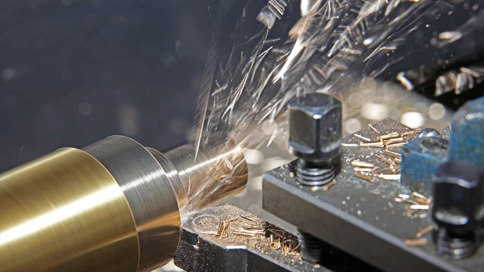
How to Improve Chip Formation and Chip Control
Good chip control comes from matching the cutting condition to the material, tool, machine, and process. The goal is not simply to make chips smaller. The goal is to make chip formation stable, predictable, and easy to evacuate from the cutting zone.
Choose Proper Cutting Parameters
Cutting speed, feed rate, and depth of cut should work together. If one parameter is suitable but the others are not, chip formation may still become unstable.
A proper feed rate helps form a chip with enough thickness to break or curl correctly. A suitable cutting speed helps control heat and material flow. A reasonable depth of cut keeps the cutting load within the capacity of the tool, fixture, and machine.
Use the Right Tool Geometry
Tool geometry strongly affects chip flow. Rake angle changes how easily the material moves over the tool face. Nose radius affects cutting contact. Edge preparation affects how the tool enters and separates the material.
Chip breakers and chip grooves are especially important for chip control. They guide the chip to curl, bend, or break in a more controlled way. The tool should match the workpiece material and the machining operation.
Improve Coolant Delivery
Coolant should reach the cutting zone effectively. It helps reduce heat, lower friction, and support smoother chip evacuation.
Coolant direction, flow, pressure, and concentration all matter. In drilling, internal turning, threading, and deep-hole machining, poor coolant delivery can quickly lead to chip blockage, overheating, and unstable cutting.
Strengthen Workholding and Machine Rigidity
A stable setup helps produce stable chips. If the workpiece, tool holder, spindle, or fixture moves under cutting force, chip thickness may change during machining.
Good workholding reduces vibration and keeps the cutting edge engaged consistently. Strong machine rigidity also helps the process remain stable during heavier cuts, interrupted cuts, or high-precision CNC machining.
Match the Machine to the Process
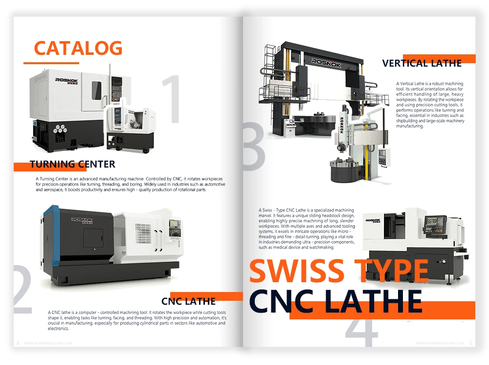
Different machining tasks need different machine structures. A CNC lathe is suitable for rotary parts. A machining center is better for complex milling, drilling, boring, and tapping in one setup. A Swiss type lathe is suitable for small, precise parts. A pipe threading lathe is designed for pipe thread machining. A vertical lathe is suitable for large disc-shaped and short rotary parts.
When the machine matches the part and process, chip formation becomes easier to control. This improves machining stability, reduces unnecessary interruptions, and supports more consistent production results.
The Role of CNC Machine Quality in Chip Formation
CNC machine quality affects chip formation because the cutting process depends on stable motion, strong support, and consistent control. Even with the right tool and parameters, weak machine rigidity or unstable movement can make chip formation less predictable.
Spindle Stability
The spindle controls tool or workpiece rotation, depending on the machining process. If spindle rotation is stable, the cutting edge engages the material more consistently.
Poor spindle stability, excessive runout, or vibration can change cutting load during machining. This may cause uneven chip thickness, unstable chip flow, and faster tool wear.
Feed System Accuracy
The feed system controls how the tool and workpiece move relative to each other. Accurate feed motion helps maintain consistent chip thickness.
If feed movement is not smooth, the tool may remove too much material in one moment and too little in the next. This can create irregular chips, vibration marks, and unstable cutting force.
Machine Rigidity
Machine rigidity allows the tool, spindle, bed, guideways, and fixture to resist cutting force. A rigid machine keeps the cutting edge in the correct position during material removal.
When rigidity is weak, deflection and vibration become more likely. The chip may change shape during the same cut because the real cutting condition is changing under load.
Chip Removal System
A good chip removal system keeps chips away from the cutting zone. Conveyors, coolant flow, machine enclosure, and chip guards all help prevent chips from accumulating around the tool, workpiece, and guideways.
This is important for continuous machining. If chips stay in the cutting area, they may be recut, scratch the surface, block coolant, or interfere with the next tool movement.
Automation and Process Consistency
CNC systems, automatic tool changers, tool magazines, and repeatable programs help keep machining conditions consistent from part to part. This consistency supports more stable chip formation during batch production.
Conclusion
Chip formation is one of the clearest signs of what is happening inside the cutting zone. It shows whether the material is being removed smoothly, whether the tool is working under stable load, and whether heat, friction, chip flow, and machine motion are under control. Good chip formation supports safer machining, longer tool life, better surface finish, and more consistent production.
For companies that want stable chip control in real production, the machine itself also matters. Rosnok provides CNC lathes, machining centers, milling machines, Swiss type lathes, pipe threading lathes, vertical lathes, and other CNC machine solutions for metal machining, helping workshops match the right equipment to the right cutting process.