In real CNC machining, the rake face affects much more than chip direction. It influences cutting force, tool wear, vibration, surface finish, and even machining cost. A well-designed rake face can help chips evacuate smoothly, reduce friction, and improve tool life. A poorly matched rake face may cause built-up edge, poor finish, unstable cutting, or premature tool failure.
This article deeply explains what the rake face is, why it matters, how it works with rake angle, and how machinists can understand it in practical cutting applications.
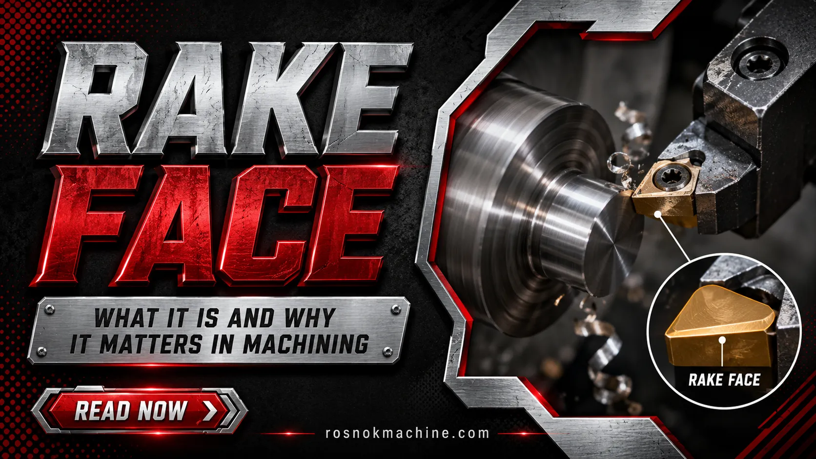
What Is a Rake Face in Machining?
In metalworking operations, the rake face can be most simply understood as the chip-guiding surface of a cutting tool. It is the specific area that directly contacts the removed material during the cutting process. As soon as the cutting edge shears material away from the workpiece, the newly formed chip flows and slides along this surface to exit the cutting zone.
It is important to recognize that the rake face is not an isolated plane. It is a core structural element within the overall tool geometry. It works together with the cutting edge, flank face, and defined rake angle to establish the initial direction of chip flow. By providing this path, the rake face forms the basic physical foundation for how material is separated and evacuated during CNC machining.

Where Is the Rake Face Located on a Cutting Tool?
The rake face is located behind the cutting edge, on the side where the chip leaves the workpiece. When the cutting edge separates material from the workpiece, the chip does not move randomly. It first contacts the rake face and then slides across this surface as it moves away from the cutting zone.
The exact shape of the rake face depends on the cutting tool. A turning tool, milling cutter, drill, and indexable insert may all have different tool structures, but the rake face serves the same basic role. It is always positioned near the cutting edge and forms the first contact path for the newly formed chip.
On an indexable insert, the rake face is usually found on the top surface or on the formed surface close to the cutting edge. This area may look flat or shaped, depending on the insert design. For visual understanding, it can be seen as the surface that sits just behind the edge and faces the direction of chip movement.
Rake Face on Turning Tools
On a turning tool, the rake face is the surface close to the cutting edge where the chip flows during external turning, internal turning, facing, or similar operations. Since the workpiece rotates and the tool feeds into the material, the chip usually moves upward or sideways along the rake face after being cut.
Rake Face on Milling Cutters
On a milling cutter, each cutting tooth has its own rake face. As the cutter rotates, every tooth enters and exits the workpiece. When a tooth cuts material, the chip forms at its cutting edge and moves along the rake face of that specific tooth.
Rake Face on Drills
On a drill, the rake face is related to the flute area near the cutting lips. After the drill cutting edge removes material, the chip moves into the flute and travels out of the hole. This makes the rake face easy to understand visually: it is the surface near the drill edge that first guides the chip into the flute path.

Why Does the Rake Face Matter in Machining?
The rake face matters because it directly affects how easily material is removed from the workpiece. When the chip slides across this surface, the tool must overcome material resistance, friction, and heat. A suitable rake face helps the cutting process feel smoother and more controlled, while an unsuitable one can make cutting heavier and less stable.
In practical machining, this surface influences several visible results. It affects whether chips leave the cutting zone smoothly, whether cutting heat builds up near the edge, and whether the tool wears quickly. It also has an indirect effect on surface quality, because unstable chip flow or excessive cutting resistance can lead to marks, vibration, or inconsistent results on the finished part.
For production workshops, the rake face is not only a tool geometry detail. It can influence tool life, machine load, machining stability, and part consistency. When the rake face matches the material and cutting condition, the process is usually easier to control. When it does not, the result may be higher tool cost, more downtime, lower efficiency, and less predictable machining quality.

Rake Face and Rake Angle: What Is the Relationship?
The rake face is a surface. The rake angle is the angle of that surface. This is the simplest way to understand their relationship. In cutting tool geometry, the rake angle describes how the rake face is tilted relative to a reference plane near the cutting edge.
This angle matters because it changes the way the tool meets the material. A different rake angle can make the cutting edge feel sharper or stronger, depending on the design. It also changes the path the chip follows as it moves across the rake face.
In other words, the rake face provides the chip-contact surface, while the rake angle defines the orientation of that surface. They should not be treated as the same concept. One is a physical face on the tool, and the other is a geometric measurement used to describe how that face is positioned.
Types of Rake Angles Related to the Rake Face
The operational characteristics of the rake face are fundamentally defined by its angle of inclination. In industrial tooling design, these geometries are classified into three primary categories, each engineered to address specific material properties and machining requirements.
Positive Rake Face
A positive rake face leans in a direction that makes the cutting edge sharper and easier to enter the material. It usually reduces cutting force and helps chips flow more smoothly. This type is often used for aluminum, copper, thin-walled parts, light cutting, and high-speed machining. Its limitation is that the cutting edge may be weaker under heavy load.
Negative Rake Face
A negative rake face gives the cutting edge more strength. It is often used for harder materials, cast iron, interrupted cutting, and heavy roughing. Because the edge is stronger, it can handle higher impact and more demanding cutting conditions. However, it usually creates higher cutting resistance and more heat than a positive rake design.
Neutral Rake Face
A neutral rake face has a rake angle close to zero. It offers a balance between sharpness and edge strength. This type is commonly used in general machining conditions where the material, cutting depth, and machine rigidity do not strongly require either a very sharp or very strong cutting edge.

How the Rake Face Controls Chip Flow
The rake face controls chip flow because every newly formed chip slides across this surface after leaving the cutting edge. Its angle, surface condition, coating, and chip breaker design all affect whether the chip moves smoothly, curls properly, or becomes difficult to evacuate.
A well-designed rake face gives the chip a controlled path out of the cutting zone. This helps reduce chip crowding around the cutting edge and makes the process more stable. In continuous CNC production, stable chip flow is important because uncontrolled chips can wrap around the tool, scratch the workpiece, or interrupt automatic machining.
Smooth Chip Evacuation
Smooth chip evacuation means the chip leaves the cutting area without blocking the tool or damaging the workpiece. The rake face helps create this path. When the surface is suitable for the material and cutting condition, chips move away more predictably and the cutting zone stays cleaner.
Chip Curling and Chip Breaking
As the chip slides along the rake face, it may curl because of the tool geometry and cutting pressure. In many tools, a chip breaker is added near the rake face to help bend and break the chip into shorter pieces. This is especially useful when machining ductile metals that tend to produce long continuous chips.
Chip Control in CNC Turning and Milling
In CNC turning, the rake face helps guide chips away from the rotating workpiece and cutting edge. In CNC milling, each tooth has its own rake face, so chip control happens repeatedly as the cutter rotates. In both cases, controlled chip flow helps maintain a safer and more consistent machining process.

How the Rake Face Affects Cutting Force and Heat
The rake face affects cutting force because it influences how easily the material shears and flows away from the cutting edge. When the chip moves across the rake face, friction is created between the chip and the tool surface. The higher this resistance becomes, the more force the machine must apply to continue cutting.
A more positive rake face usually reduces cutting force because the tool enters the material more easily. This can make machining smoother, especially with softer or more ductile metals. A more negative rake face gives the cutting edge greater strength, but it often increases cutting resistance because the material needs more force to deform and separate.
Heat is closely connected to this process. More friction on the rake face usually means more heat near the cutting edge. If heat becomes excessive, it can reduce tool hardness, damage coatings, affect dimensional stability, or cause thermal deformation in the workpiece. This is why rake face geometry must match the material, cutting load, and machine rigidity.
A stable CNC machine also helps the rake face perform as intended. A rigid spindle, strong machine bed, and accurate feed system reduce vibration and allow the cutting tool to maintain steady contact with the material. When tool geometry and machine stability work together, cutting force and heat are easier to control.
How the Rake Face Influences Tool Wear and Tool Life
The rake face is one of the main wear areas on a cutting tool because chips slide across it at high speed under pressure. During this contact, friction and heat gradually remove tool material from the rake face. Over time, this can change the tool geometry and reduce cutting performance.
Crater Wear on the Rake Face
Crater wear is a common wear pattern that forms on the rake face. It appears as a shallow depression where the chip repeatedly rubs against the tool surface. If crater wear becomes severe, it weakens the cutting edge and may lead to faster tool failure.
Built-Up Edge on the Rake Face
Built-up edge happens when workpiece material sticks to the rake face near the cutting edge. This is more common when machining sticky materials or using unsuitable cutting conditions. Once built-up edge forms, the tool no longer cuts with its original geometry, which can reduce accuracy and surface quality.
Coating Damage and Heat Wear
Many cutting tools use coatings to reduce friction and improve heat resistance. However, excessive heat or poor chip flow can damage the coating on the rake face. Once the coating breaks down, wear may accelerate, tool life becomes shorter, and tool changes become more frequent.

How the Rake Face Affects Surface Finish
The rake face does not directly create the final machined surface, but it strongly influences the conditions that affect surface finish. When chips move smoothly across the rake face, the cutting process is more stable. When chip flow becomes unstable, the finished surface is more likely to show scratches, marks, or irregular texture.
Poor rake face conditions can also lead to built-up edge. When material sticks near the cutting edge, the tool no longer cuts cleanly. This can change the effective cutting shape and produce rougher surface roughness, inconsistent dimensions, or visible tool marks on the part.
Cutting resistance is another factor. If the rake face causes excessive resistance, vibration may increase during machining. This can leave chatter marks or uneven patterns on the machined surface. For this reason, a suitable rake face helps support better cutting stability, better surface finish, and more consistent CNC machining quality.
Common Rake Face Problems in Machining
In practical manufacturing environments, an improperly specified rake face geometry quickly manifests as observable machining failures. Identifying these operational issues on the shop floor is the first step toward correcting your tooling strategy before they cause severe production bottlenecks.
Poor Chip Control
The most visible symptom of an inadequate rake face is the generation of long, continuous ribbons of metal. These uncut chips inevitably tangle around the machine spindle or pack tightly inside the work envelope, forcing automated production cycles to halt. This failure is frequently the result of a geometric angle or a molded chip breaker topography that does not correctly match the applied feed rate and depth of cut.
Built-Up Edge
When this issue occurs, the machined surface becomes abruptly rough, and dimensional accuracy fluctuates unpredictably. Visual inspection of the insert will reveal workpiece material pressure-welded directly to the cutting tip. This problem is highly common when machining sticky, ductile alloys at low cutting speeds using an insufficiently positive rake angle or a tooling surface that lacks adequate lubricity.
Excessive Cutting Heat
If the cutting tool degrades prematurely and the applied protective coatings peel away rapidly, the rake face is likely generating uncontrollable friction. This excessive thermal energy causes the workpiece to suffer from thermal expansion, making it difficult to hold tight tolerances. It is often caused by utilizing a negative rake angle that aggressively pushes rather than cleanly shears the material.
Fast Tool Wear
The rapid onset of deep cratering, micro-chipping along the cutting edge, and a sudden decline in overall part quality indicate that the guiding surface is deteriorating under the machining load. When the structural strength of the selected geometry does not align with the hardness of the workpiece material or the dynamic impact of the cutting parameters, catastrophic tool failure is imminent.

How to Choose the Right Rake Face Geometry
Selecting the optimal tool geometry requires evaluating the specific variables of your manufacturing environment. For production engineers, making the correct tooling choice depends on a careful analysis of the workpiece material, the specific cutting operation, and the structural capabilities of your facility’s equipment.
Based on Workpiece Material
Soft and ductile materials, such as aluminum and copper, usually need a sharper and smoother positive rake face to reduce cutting resistance and help chips flow easily. Stainless steel often requires a balanced design because it can be sticky and work-harden easily. Cast iron and hard steel usually need a stronger edge, better heat resistance, and a more stable rake face geometry.
Based on Machining Operation
Finishing operations usually benefit from lower cutting force and smoother chip movement, so the rake face should support clean and stable cutting. Roughing operations require more edge strength because the tool removes more material and faces heavier loads. In high-speed cutting, heat control and chip evacuation become more important. In deep-hole or internal machining, the rake face must help chips leave a limited space efficiently.
Based on Machine Rigidity
Machine rigidity also affects rake face selection. A rigid CNC machine can support stronger cutting loads and more demanding tool geometries. If the machine, fixture, or setup is not rigid enough, excessive cutting resistance may cause vibration. For stable machining, the rake face geometry should match not only the tool and material, but also the spindle, fixture, and overall machine condition.

Conclusion
The rake face may look like a small detail on a cutting tool, but it plays a quiet and decisive role in machining quality. It guides chip flow, influences cutting force, affects heat generation, and contributes to tool life and surface finish. Understanding the rake face helps machinists read tool geometry more clearly and make better decisions when selecting cutting tools, cutting parameters, and machining strategies.
However, even the most perfectly engineered tool geometry cannot achieve its full potential without an exceptionally stable mechanical foundation. This is where industrial equipment from manufacturers like Rosnok becomes an integral part of the machining equation. By producing rigid, high-precision CNC machine tools, Rosnok provides the structural integrity required to eliminate vibration under heavy cutting loads, ensuring that every optimized cutting angle translates directly into flawless, continuous manufacturing output.