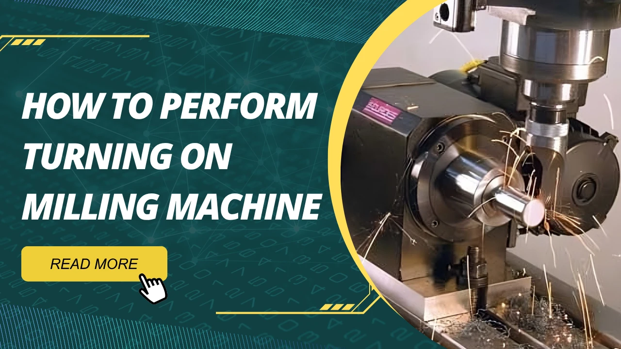
To perform turning on a milling machine, the key is to make the workpiece rotate while keeping the cutting tool stationary. This can be done by mounting the workpiece on a rotary table, a 4th-axis attachment, or a dividing head driven by the milling machine’s control system. Then, a lathe-style cutting tool is rigidly clamped to the milling machine’s worktable using a custom fixture or precision vice. With the correct alignment and feed direction, this setup allows you to execute basic turning operations—such as facing, straight turning, or contour shaping—on a milling platform. However, attention must be paid to cutting forces, spindle speed limits, and clamping rigidity to ensure safe and accurate results.
Why Perform Turning on a Milling Machine?
In a real-world production environment, it’s not uncommon to encounter scenarios where a lathe isn’t available, yet a workpiece demands light turning operations. Or you might be dealing with a complex part that requires both milling and turning features—switching between machines risks alignment errors and wastes valuable time. That’s when turning on milling machine setups become not only useful, but essential.
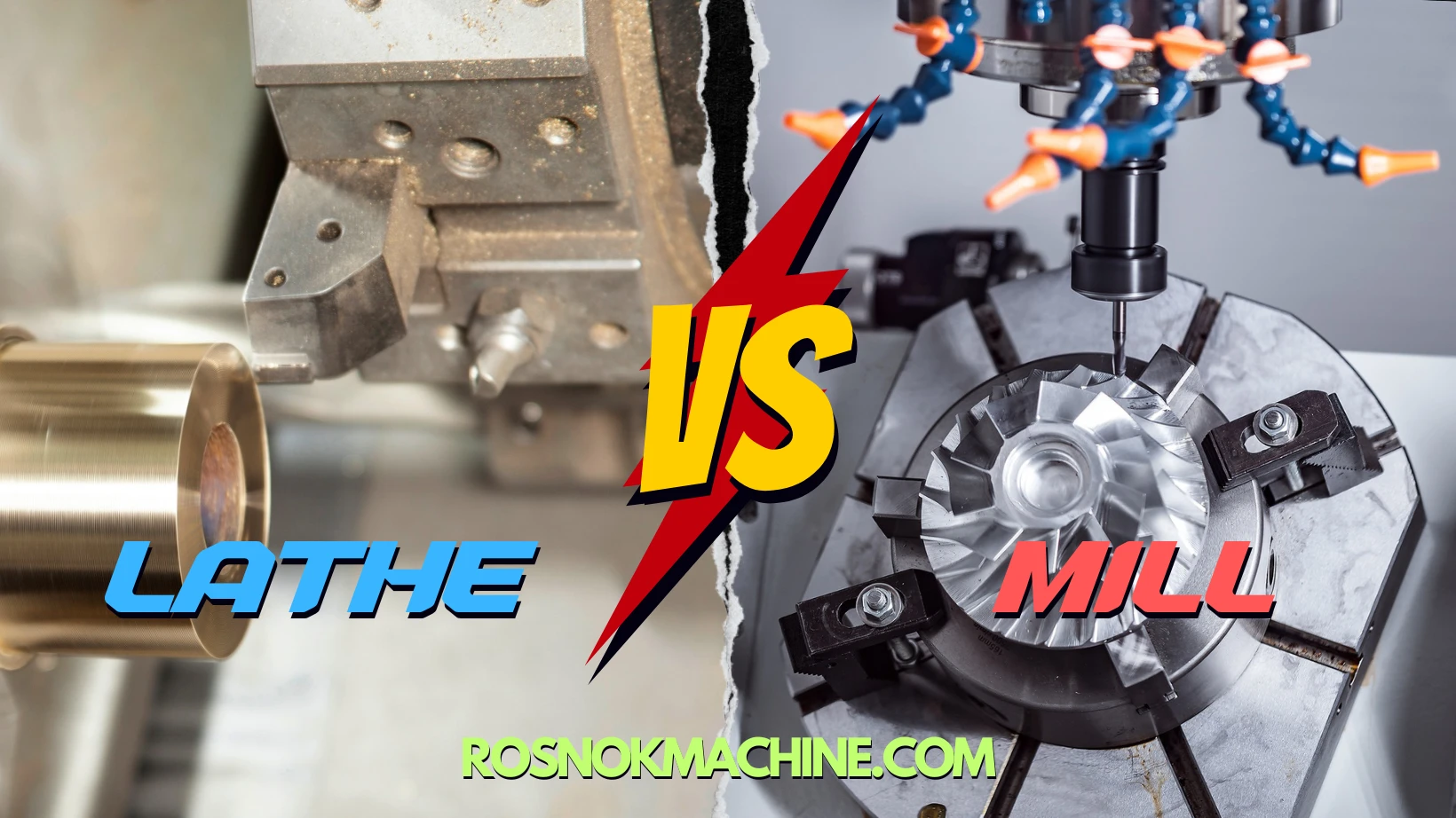
Turning on milling machine refers to a process where the workpiece is made to rotate—typically using a rotary table or 4th-axis—while a static turning tool is mounted securely on the milling machine’s table or fixture. This setup replicates certain lathe-like operations without actually using a lathe. It’s not a full substitute, but in many situations, it serves as a highly effective and flexible alternative.
Based on extensive industry usage and feedback from machine shops and engineers, the following are the most common scenarios where turning on a milling machine proves to be a practical and cost-effective solution.
To Complete Multi-Surface Machining in One Setup
Some parts require both turning and milling—such as a flange with a concentric face, a shaft with key slots, or components with both round and flat features. Traditionally, this would mean turning on a lathe first, then transferring the part to a mill. Each transfer introduces alignment errors, setup time, and potential scrap.
When the turning operation can be done directly on the milling machine, all surfaces can be machined in one clamping. Especially with a rotary table or 4th-axis, you can rotate the workpiece while keeping it referenced from the same base—maintaining precision across all features.
When a Lathe Is Unavailable or Inconvenient
Not every shop owns both a CNC lathe and a CNC mill. In smaller operations, research labs, or prototyping departments, it’s common to have a vertical milling machine but no lathe. In these cases, using the mill for light turning with custom fixturing and a rotary attachment is a viable workaround.
This is particularly true for small diameters, short workpieces, or when the turning operation is shallow—such as facing, chamfering, or removing excess material around a round boss. Turning on milling machine becomes a low-cost, low-complexity way to get the job done.
For Localized Turning on Complex or Asymmetric Parts
Some parts cannot easily be fixtured in a lathe—think of large die molds with a circular feature, or asymmetric components that need localized contour turning. In these cases, the milling machine offers more flexibility with open access and table space.
By fixing the turning tool in a vice or fixture and rotating the part precisely using a 4th-axis or rotary table, you can perform turning operations exactly where needed, without repositioning the entire part multiple times. This is one of the most underrated use cases for turning on a milling machine.
To Increase Efficiency and Eliminate Downtime
In high-throughput environments, efficiency matters more than anything. Each time you switch machines, you lose precious minutes—sometimes hours. With a hybrid setup that supports both milling and turning operations, you can run jobs faster, eliminate transfer steps, and reduce risk of misalignment.
This works especially well in production cells where parts must be delivered on tight deadlines, and where one machine is expected to do the job of two. While turning on a milling machine may not match the output of a lathe in pure turning cycles, it greatly boosts operational flexibility.
To Expand Capabilities Without Buying a New Machine
Many manufacturers question whether a full mill-turn machine is necessary to handle certain hybrid parts. In practice, the answer often depends on the complexity of the required turning operations. For many cases, it is entirely feasible to perform light-duty turning on an existing milling machine with the appropriate setup and tooling.
Turning on milling machine is not about replacing dedicated equipment. It’s about giving your team options—especially when the job doesn’t justify new hardware, or when the existing milling platform has unused capacity.
In short, turning on milling machine setups offer practical benefits in terms of flexibility, precision, and workflow efficiency. But it’s important to recognize this is not a one-size-fits-all method. There are limitations. It’s not intended for heavy-duty turning or long shafts. Instead, think of it as a smart, adaptable technique for solving real production problems when a full lathe isn’t available—or necessary.

What Turning Operations Can Be Performed on a Milling Machine?
Turning on milling machine is not limited to a single type of operation. Depending on the equipment configuration, fixture stability, and control over the rotary axis, a range of turning processes can be performed directly on a milling platform. These operations replicate many of the functions typically handled by a lathe, though often within more limited parameters.
Below are the most common turning operations that can be achieved on a milling machine, especially when using a rotary table or 4th-axis setup. While each has specific requirements and limitations, they can be highly effective for light to moderate machining tasks.
Facing
Facing is one of the simplest and most common turning operations. It involves machining the end face of a cylindrical part to create a flat surface. On a milling machine, facing is typically performed by fixing the cutting tool on the table and rotating the workpiece using a rotary axis. The cutting path is controlled along the Z-axis while the part rotates horizontally.
This operation is useful for preparing the end of shafts, removing excess material from the face of round components, or squaring off rough stock. However, due to limitations in rotational speed and rigidity, it is recommended to use shallow depth of cut and moderate feed rates.
End Facing
Similar to standard facing, end facing refers to turning the face of a part that is mounted perpendicular to the spindle axis. In a milling setup, this can be done by placing the part vertically using a rotary fixture or angle plate and feeding the tool horizontally into the rotating workpiece.
End facing is typically used in mold components, circular base plates, or adapter flanges that require smooth, flat surfaces on the ends. Care must be taken to ensure the part is square and rigidly clamped to avoid runout or vibration.

External Diameter Turning
External diameter turning (or OD turning) involves reducing the diameter of a cylindrical part. This operation is more complex on a milling machine, as it requires accurate synchronization between the rotary motion of the part and the feed motion of the cutting tool.
Using a 4th-axis or motorized rotary table, the part is spun slowly while the tool feeds parallel to the axis of rotation. This allows gradual material removal around the outer diameter. OD turning on a milling machine is ideal for short shaft sections, small bosses, or surface cleanup on already rough-turned parts.
However, because milling machines are not built for continuous rotary cutting, the spindle speed should be limited, and the tool engagement must be carefully controlled. Proper fixturing and low radial cutting forces are essential to ensure accuracy and safety.
Chamfering and Grooving
Chamfering is used to create beveled edges, typically at 45 degrees, while grooving involves cutting a recess or slot into the outer surface of a part. These operations are straightforward to perform in turning mode using a milling machine.
The cutting tool is fixed at a specific angle or offset, and the workpiece is rotated at a controlled speed. For chamfering, the tool approaches the edge diagonally; for grooving, it plunges radially into the rotating part.
Both chamfering and grooving require accurate tool positioning and rigid support, especially when working on small-diameter parts. They are commonly used for deburring, creating assembly reliefs, or preparing parts for O-rings and retaining clips.
Eccentric Turning
Eccentric turning involves machining a cylindrical surface that does not share the same center as the main part axis. This is often required in components like camshafts, off-center bushings, or specialized drive elements.
In a milling environment, eccentric turning can be achieved by offsetting the rotary fixture or 4th-axis centerline from the tool path. This controlled offset allows machining of circular features that are deliberately misaligned from the primary axis.
While eccentric turning is complex and demands high-precision fixturing, it demonstrates the flexibility of turning on milling machine platforms when combined with intelligent programming and precise setup.
Contouring and Profiling
Contouring refers to the generation of non-straight or curved surfaces, often with continuously changing radii. In turning mode, this can include creating blended tapers, radiused shoulders, or complex surface transitions.
Using CAM software and a synchronized rotary setup, a milling machine can trace intricate profiles along a rotating workpiece. This is particularly useful in prototyping or low-volume parts where lathe automation is not available, but shape accuracy is essential.
Profiling operations must account for cutting force direction, especially since the tool does not rotate. Tool wear and thermal deflection can also affect accuracy, so careful parameter tuning is necessary.
Limitations to Consider
Although many turning operations can be performed on a milling machine, the following limitations should always be kept in mind:
- Milling machines lack the high-speed rotary spindles of dedicated lathes, making them unsuitable for aggressive turning or large-diameter parts.
- Cutting forces must be minimized to avoid excessive vibration or fixture slippage.
- Tool holding is less flexible than in lathes, and clearance must be checked in every axis.
- Rotary axes have limited torque and may not sustain heavy or deep cuts over time.
Therefore, turning on a milling machine is best suited for light-duty work, low-volume runs, prototype development, or special parts where traditional lathe setups are impractical.
Method 1: Using a Rotary Table for Turning
One of the most accessible ways to perform turning on milling machine setups is by utilizing a rotary table. This method allows the workpiece to rotate slowly while a stationary cutting tool performs turning operations. It enables basic lathe-like machining on a milling platform, especially suitable for light-duty applications when a dedicated turning center is unavailable.
In this configuration, the rotary table spins the workpiece, while the tool remains fixed. This mirrors the same cutting principle as on a traditional lathe—where the material rotates against a non-rotating tool. By enabling controlled rotation on a milling machine, a rotary table expands its functional scope to include essential turning tasks.
This method is often used to machine small round features, such as end faces, short cylindrical sections, or turned profiles on parts that require milling and turning features in a single setup.
Equipment and Setup
The rotary table is mounted securely on the milling machine’s bed. Proper alignment is critical to ensure the rotary motion is concentric and parallel to the intended tool path. Depending on its design, a rotary table can be:
- A manually controlled rotary table, suitable for simple positioning and low-speed turning
- A motorized rotary table with programmable indexing, which allows predefined angular steps during machining
Workholding is usually accomplished with:
- Standard lathe chucks bolted to the rotary table
- Faceplates with clamps or T-slot bolts
- Soft jaws or custom fixtures for irregular parts
The cutting tool is mounted rigidly to the machine table using a clamping block or custom fixture. Proper tool height, clearance, and alignment with the rotary axis are essential for safe and accurate machining.
This method is best suited to parts with moderate diameters and requires very stable fixturing to prevent vibration during cutting.

Operational Technique
Turning with a rotary table differs from conventional milling in that the material rotates while the tool advances linearly. Since the rotary motion is slower and less powerful than a lathe spindle, cutting parameters must be conservative:
- Rotational speed: 30–200 RPM depending on diameter and material
- Depth of cut: Light cuts only (0.1–0.5 mm per pass)
- Feed: Steady manual or automated feed along the machine’s linear axes
Common operations include:
- Facing: Machining a flat surface on the end of a cylindrical part
- External turning: Reducing the outer diameter of a short round feature
- Chamfering: Adding bevels to edges or shoulders
- Grooving: Cutting narrow, circular recesses or reliefs
Since milling machines are not designed for high radial cutting forces during rotation, rigidity is critical. Chatter, deflection, or slippage can easily lead to dimensional errors or tool damage.
Advantages of the Rotary Table Method
Despite its simplicity, this method offers practical advantages:
- Cost-effective: No need for an additional turning machine
- Flexible: Easy to integrate into existing setups
- Precise: Suitable for prototyping and light cylindrical features
- Efficient: Reduces re-clamping between machines for combined mill-turn parts
It is particularly useful for shops that need occasional turning on parts that are primarily milled but include a few circular features.
Limitations
Like any workaround method, rotary table turning has constraints:
- Not suitable for heavy cutting or large parts
- Limited by torque and speed of the rotary table
- Setup is manual and time-consuming
- No automated control over continuous rotary motion
- Accuracy depends entirely on operator setup and part clamping
For jobs requiring speed, consistency, and deep material removal, this method cannot replace a lathe or CNC 4th-axis solution. But for occasional low-volume needs, it remains a valuable technique.

Method 2: Using a CNC 4th-Axis for Semi-Automated Turning
A more advanced approach to turning on milling machine setups involves the use of a CNC-controlled 4th-axis. Unlike manual or semi-manual rotary tables, a CNC 4th-axis allows precise and programmable rotation of the workpiece in synchronization with the machine’s linear movements. This enables more complex and consistent turning operations without operator intervention during cutting.
The 4th-axis acts as an additional rotary motion, typically installed perpendicular to the main spindle axis on a vertical machining center or horizontally on a gantry-type machine. It allows the workpiece to rotate around a fixed axis, while the tool moves along programmed paths in X, Y, or Z.
This method bridges the gap between traditional milling and full lathe functionality, giving users the ability to handle cylindrical features, concentric surfaces, and rotational profiles more efficiently.
Setup and Integration
To perform turning on a milling machine using a 4th-axis, several critical components must be integrated correctly:
- CNC 4th-axis rotary unit: Must be capable of continuous rotation (not just indexing) and rated for the torque required by the operation
- Tailstock or steady rest (optional): Supports long parts to prevent deflection or chatter during rotation
- CNC controller with 4th-axis support: Required to synchronize rotary motion with tool feed
- Tool holding fixtures: Rigid brackets or tool blocks mounted on the table to secure the turning tool
The workpiece is clamped into a chuck or fixture mounted on the 4th-axis rotary unit. If the part is long, a tailstock on the opposite end helps maintain concentricity and stability.
Unlike traditional milling, the tool remains stationary in the spindle while the workpiece rotates. In this setup, the cutting action occurs as the workpiece spins and the tool feeds axially, radially, or along a defined contour.

Common Applications
Using a CNC 4th-axis enables higher precision and greater repeatability than manual rotary tables. Common turning operations performed with this method include:
- Outer diameter (OD) turning: Machining cylindrical surfaces to specified diameters
- Taper turning: Creating angled profiles along the shaft length
- Facing: Cleaning or flattening the end face of rotating components
- Threading: Cutting threads using single-point tools and synchronized motion
- Profiling: Generating custom surface shapes and step transitions
These operations are particularly useful when producing parts with rotational symmetry, such as bushings, shaft collars, threaded adapters, and cylindrical connectors.
For complex parts that combine prismatic and round features—such as valves, pump components, and aerospace fittings—a 4th-axis setup on a milling machine enables seamless integration of turning steps without part repositioning.
Programming Considerations
To achieve smooth and accurate results, programming must coordinate the 4th-axis movement with toolpath strategies:
- G-code: CNC programs must include commands for axis A (the 4th-axis) and manage its speed and direction precisely
- CAM software: Most modern CAM platforms support simultaneous 4-axis operations and allow visual simulation before machining
- Feed and speed control: Must account for material type, tool geometry, and diameter of rotation to avoid excessive tool pressure
It’s important to apply conservative cutting parameters, especially when the rotary unit has limited torque or when cutting hard materials. Thermal stability and tool wear should be monitored closely to maintain consistency across production batches.
Benefits of 4th-Axis Turning
Compared to manual rotary setups, the CNC 4th-axis method offers several clear advantages:
- Higher accuracy: Programmable motion reduces human error and ensures consistent results
- Better productivity: Automated cutting eliminates the need for constant operator input
- Multi-surface machining: Allows machining of complex rotational profiles that would be difficult with a lathe
- Improved alignment: Turning and milling features can be created in a single setup, reducing tolerancing errors
- Expanded part geometry: Supports eccentric, tapered, or stepped profiles with minimal re-fixturing
In small-batch production and prototyping environments, this approach enables the machine to handle a broader variety of part features with fewer tool changes and setup adjustments.
Challenges and Limitations
While CNC 4th-axis turning is powerful, it does come with several important constraints:
- Torque and rigidity: Most 4th-axis units cannot handle heavy or deep cuts
- Cost and integration: Requires a machine equipped with 4th-axis hardware and a compatible controller
- Programming complexity: Operators must be trained in multi-axis machining and CAM software
- Tool clearance: Limited space for tool holders and fixtures may restrict geometry
This method is best suited for precision components that require both milled and turned features in small to medium volumes. It is not intended to replace dedicated lathes for high-speed or large-diameter operations.
When applied appropriately, turning on milling machine platforms using a CNC 4th-axis allows machine shops to take on a wider range of workpieces without adding separate turning centers.

Safety Considerations and Limitations
When performing turning on milling machine setups—whether with a rotary table or CNC 4th-axis—special attention must be paid to safety. Unlike lathes, milling machines are not inherently designed for continuous rotational cutting. As such, improper setup or tool selection can lead to equipment damage, tool failure, or even serious injury.
This section outlines the core safety concerns and practical limitations of milling-based turning operations.
Inadequate Workholding and Risk of Workpiece Ejection
Most milling machine setups lack active spindle clamping feedback mechanisms found in lathes. If the workpiece is not securely fixed to the rotary table or 4th-axis chuck, the centrifugal force generated during rotation—even at low RPMs—can cause the part to loosen or fly off.
Common causes include:
- Improper chucking or under-tightening
- Mismatch between chuck type and workpiece geometry
- Unbalanced fixtures or eccentric loading
Safety Tip: Always use mechanical stops or tailstock support where possible, verify concentricity, and conduct a low-RPM test rotation before starting the cut.
Tool Rigidity and the Risk of Chatter or Tool Breakage
Unlike lathes, milling machines do not feature robust toolposts designed for radial cutting forces. As a result, turning tools mounted to the milling table may lack the stiffness required to resist deflection, vibration, or torque loads.
This is especially dangerous when:
- Using long, unsupported tool holders
- Cutting hard or tough materials
- Attempting deep or aggressive cuts
Recommended Practices:
- Use short, rigid tool holders with wide contact surfaces
- Minimize tool overhang
- Choose positive rake carbide inserts designed for interrupted cuts
- Monitor cutting sound for early signs of chatter

Operator Error from Non-Turning Machine Interface
Operators accustomed to milling operations may underestimate the dynamics of rotary cutting. Key risks include:
- Incorrect tool height or angle (leading to poor surface finish or tool wear)
- Incorrect spindle orientation or axis direction
- G-code misinterpretation for A-axis or rotary table motion
- Mistaking part rotation speed with tool feed direction
Such errors can result in:
- Part scrapping
- Tool crashes
- Excessive wear on rotary table bearings
Training and simulation tools are recommended before running turning operations on unfamiliar equipment.
Material and Geometry Limitations
Milling-based turning is not a universal replacement for a lathe. There are clear physical and performance boundaries that should be respected.
Limitations include:
| Limitation Type | Description |
|---|---|
| Diameter | Generally not suitable for parts > 150–200 mm OD |
| Length | Limited by table space and lack of tailstock on most mills |
| Cutting Depth | Cuts > 1 mm/pass can generate unstable radial force |
| Materials | Best suited for aluminum, brass, and mild steel |
| Surface Finish | Difficult to achieve fine finish on long surfaces |
For aggressive material removal, especially with hard alloys or long shafts, a traditional lathe is strongly recommended.
General Guidelines for Safe Use
- Never exceed 300 RPM unless the rotary system is specifically designed for higher-speed continuous rotation
- Avoid unsupported overhanging parts
- Always verify toolpath simulation before first run
- Use shields or barriers when testing a new setup
- Monitor spindle and table temperatures for signs of overload
- Stop the machine immediately if unusual vibration, noise, or tool deflection occurs
Final Note
Milling machines adapted for turning are valuable tools—but must be treated as limited-purpose setups, not lathe substitutes. With proper tooling, conservative parameters, and safety-first operation, they can effectively handle secondary or hybrid operations without introducing undue risk.
Conclusion
Blending precision with practicality, turning operations on a milling machine have quietly reshaped how modern shops approach complex, low-volume parts. For those facing production flexibility demands, tight deadlines, or space constraints, these hybrid setups unlock new possibilities without the need to invest in additional machines. While they don’t replace traditional lathes, they offer an efficient workaround—bridging design complexity and resource efficiency in a way that’s both smart and scalable.
This integration of turning capabilities into milling workflows calls for more than just creativity—it requires dependable, high-performance machine tools. For manufacturers looking to expand in this direction, working with proven suppliers of CNC milling machines, lathes, and hybrid systems ensures both safety and repeatability. That’s why many global workshops rely on experienced builders like Rosnok, whose machines are engineered for precision, built for industrial scale, and trusted across industries where reliability is not optional.