In the following sections, the causes of backlash, its impact on machine performance, the working principles of backlash compensation within CNC systems, and the practical limitations of compensation strategies will be examined in detail.
What Is Backlash in CNC Machines?
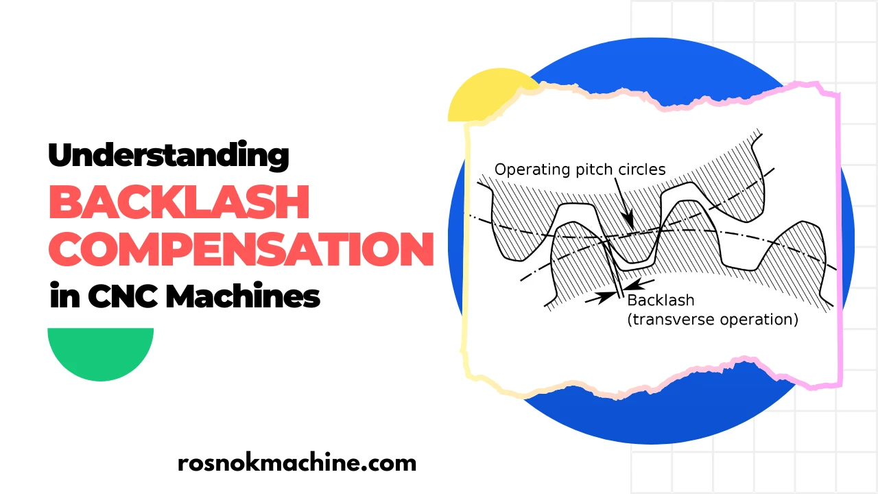
Backlash in CNC machines refers to mechanical clearance within the motion transmission system. It is the small gap between mating components that prevents immediate motion transfer when direction changes.
In CNC machine tools, backlash commonly exists in ball screw assemblies, gear trains, and mechanical couplings. Even in preloaded systems, a minimal amount of clearance may still remain due to manufacturing tolerances or long-term wear.
The most critical moment when backlash becomes visible is during direction reversal. When an axis changes direction, the servo motor may rotate, but the load does not immediately follow. The gap must first be taken up before actual linear movement begins. This delay is known as lost motion.
It is important to distinguish backlash from general positioning error. Positioning error may result from servo tuning, thermal expansion, structural deformation, or encoder resolution limits. Backlash, however, is specifically caused by mechanical clearance in the transmission path. It is directional and most evident during reversal.
Backlash is not constant over the lifetime of a machine. It typically increases over time due to ball screw wear, preload reduction, lubrication degradation, and repeated load cycles. As components gradually lose their tight mechanical fit, the clearance grows, and lost motion becomes more pronounced.
Understanding this mechanical behavior is essential before discussing compensation strategies. Backlash originates from physical structure, not from control logic.

Why Backlash Affects Machine Positioning Accuracy
Backlash directly influences machine positioning accuracy because it introduces directional deviation during axis reversal. When motion changes direction, the mechanical clearance must be absorbed before actual movement begins. This creates a gap between commanded position and actual position.
In linear positioning tasks, this results in repeatability errors. The axis may reach the same coordinate from one direction but deviate when approaching from the opposite direction. This inconsistency reduces positioning reliability.
Backlash becomes more critical during circular interpolation. When two axes reverse direction while machining arcs, lost motion can distort the programmed radius. The result may appear as ovality, corner marks, or measurable contour deviation. This effect is most evident at quadrant transitions, where simultaneous axis reversal can magnify directional deviation.
Contour machining is also sensitive to backlash. In multi-axis toolpaths, frequent micro-direction changes amplify the effect of mechanical clearance. While backlash is a localized reversal error, repeated direction changes in complex 3D toolpaths can lead to visible trajectory distortion.
Surface finish is another indirect indicator. During reversal points, slight hesitation or delayed engagement may leave visible marks on the workpiece surface, especially in precision finishing operations.
Over time, increasing backlash reduces dimensional repeatability across production batches. Even if average dimensions remain within tolerance, variation may widen, leading to unstable quality control.
Backlash does not always cause dramatic error. However, in high-precision CNC machining, even small directional deviation can affect tolerance control.

How Backlash Compensation Works in CNC Systems
Backlash compensation is implemented within the CNC control system to correct lost motion caused by mechanical clearance. It does not eliminate the physical gap. Instead, it modifies the commanded axis movement to offset the expected directional deviation.
The compensation process begins with direction change detection. When an axis reverses motion, the control system identifies the reversal event. This moment is critical because backlash only affects movement during directional transition.
Once reversal is detected, the CNC system introduces a calculated offset into the commanded position. The offset value corresponds to the measured backlash amount for that axis. In pulse-based systems, this appears as additional compensation pulses. In position-based systems, it is applied as a small positional shift.
The servo system then executes the corrected command. The servo motor moves slightly beyond the original target position to absorb the mechanical clearance. Once the gap is taken up, normal motion continues. To the operator, the movement appears continuous, but internally the control system has inserted a corrective adjustment.
The compensation value is typically stored as a parameter within the CNC control. It is defined separately for each axis, since backlash varies depending on mechanical configuration and wear condition. These values are typically determined through precision measurement procedures performed during machine setup or maintenance.
Two main compensation modes are commonly used. In one-direction compensation, correction is applied only when the axis reverses into a specific direction. In two-direction compensation, separate values may be assigned for both positive and negative reversals. The selection depends on machine structure and control capability.
Backlash compensation improves positioning consistency during reversal. However, it operates within the control layer and assumes that mechanical clearance remains stable within a predictable range.

Methods of Measuring Backlash in CNC Machines
Accurate backlash compensation depends on precise measurement. Before any parameter adjustment, the actual mechanical clearance must be quantified under controlled conditions.
Dial Indicator Method
The dial indicator method is the most common practical approach. A precision dial indicator is mounted against a stable reference surface, typically aligned with the axis being tested.
The axis is moved in one direction to eliminate clearance, then reversed slowly. During measurement, the axis is typically controlled using MDI mode or low-speed jogging to minimize inertia effects and ensure accurate indicator readings. The indicator reading difference between command movement and actual movement reveals the backlash value. This method is simple and widely used during routine maintenance.
However, it measures localized mechanical play and may not capture dynamic behavior under load.
Laser Interferometer Measurement
Laser interferometers provide high-precision axis positioning measurement. During forward and reverse motion tests, positional deviation is recorded across the entire travel range.
Backlash can be identified as the difference between forward and reverse positioning curves at identical coordinates. This method offers micron-level accuracy and is commonly used during machine calibration or factory acceptance testing.
It provides a comprehensive evaluation but requires specialized equipment.
Ball Bar Test
A ball bar test evaluates circular interpolation accuracy. The machine performs a programmed circular motion while a telescopic measurement device records radial deviation.
Backlash effects typically appear at quadrant transitions, where axis reversal occurs. On ball bar plots, backlash often appears as quadrant spikes at these reversal points, indicating sudden directional deviation. This method evaluates backlash influence in dynamic motion rather than isolated axis movement.
CNC Parameter-Based Estimation
Some CNC systems allow estimation of backlash through internal diagnostic functions. By analyzing reversal deviation data, the control system can approximate mechanical clearance values.
This method is convenient but should be validated with external measurement for high-precision applications.
Acceptable Backlash Tolerance Ranges
Acceptable backlash values vary depending on machine type, axis configuration, and required precision level. High-precision machining centers typically require minimal directional deviation, while heavy-duty machines may tolerate slightly larger mechanical clearance.
The key objective is consistency and predictability rather than absolute zero clearance.

Types of Backlash Compensation Strategies
Backlash compensation can be implemented through different approaches depending on control capability and machine structure. These strategies operate at either the software level, the servo control level, or the mechanical design level. It is important to distinguish between compensating clearance and physically eliminating it.
Parameter-Based Compensation
Parameter-based compensation is the most common method in standard CNC systems. A fixed backlash value is entered into the control parameters for each axis.
When direction reversal is detected, the CNC automatically applies the predefined offset. This approach assumes that mechanical clearance remains stable and predictable within a certain range.
It is simple, widely supported, and suitable for machines with moderate wear levels. However, it does not adapt dynamically to changing mechanical conditions.
Electronic Compensation in Servo Systems
In more advanced systems, backlash compensation may be integrated into the servo control loop. Encoder feedback and position monitoring allow more refined correction during reversal.
Instead of applying a single static offset, the control system can coordinate compensation with servo response characteristics. This improves smoothness and reduces abrupt motion during directional changes.
Electronic compensation enhances motion stability but still relies on accurate baseline measurement of mechanical clearance.
Mechanical Elimination vs Software Compensation
Mechanical solutions aim to reduce or eliminate backlash at the source. Common methods include preloaded ball screws, double-nut assemblies, and gear preload mechanisms.
Preloading increases contact pressure between mating components, minimizing clearance and reducing lost motion during reversal.
Software compensation corrects the symptom. Mechanical preload reduces the cause. In high-precision CNC machine tools, both approaches are often combined.
Compensation should not be viewed as a substitute for sound mechanical design. It is a corrective strategy that operates within the limits defined by the physical transmission system.

Limitations of Backlash Compensation
Backlash compensation improves positioning consistency, but it does not remove mechanical clearance. It operates within predefined parameters and assumes that the mechanical condition of the transmission system remains stable.
Compensation Cannot Repair Mechanical Wear
Compensation corrects directional deviation at the control level. However, if ball screws, nuts, or gears are severely worn, mechanical instability may exceed the compensation range.
When clearance becomes excessive, lost motion may no longer be predictable. In such cases, software correction cannot restore structural rigidity or repeatability.
Excessive Backlash and Servo Instability
Large compensation values can influence servo behavior during reversal. If the offset required is significant, abrupt positional correction may introduce transient motion irregularities.
While modern controls manage this effectively, excessive mechanical clearance increases the risk of unstable motion response, especially under high-speed or high-load conditions.
Overcompensation Risks
Incorrect parameter settings may result in overcompensation. If the compensation value exceeds actual clearance, the axis may overshoot during reversal.
This can create bidirectional positioning error rather than eliminating it. Accurate measurement and validation are therefore essential for reliable compensation.
Interaction with Thermal and Structural Effects
Backlash compensation addresses directional clearance. It does not correct thermal expansion, structural deformation, or dynamic deflection under cutting load.
In high-precision machining, multiple error sources may interact. Compensation for backlash cannot resolve errors originating from other mechanical or environmental factors.
Long-Term Degradation
Mechanical systems change over time. Wear progression, lubrication breakdown, and preload reduction gradually alter clearance values.
If compensation parameters are not periodically reviewed, correction accuracy may drift. Compensation assumes stability; aging mechanical systems reduce that stability.

When Should Backlash Be Mechanically Repaired Instead of Compensated?
Backlash compensation is effective only within a predictable mechanical range. When mechanical clearance exceeds stable limits, software correction alone is no longer sufficient.
Excessive Compensation Values
If compensation parameters become unusually large compared to typical machine specifications, it indicates significant mechanical wear.
Large correction values increase the likelihood of unstable reversal behavior and inconsistent positioning. When compensation values must be repeatedly increased over time, mechanical inspection becomes necessary.
Inconsistent or Unstable Reversal Behavior
Compensation assumes repeatable directional deviation. If axis reversal produces irregular or fluctuating positional errors, the mechanical condition may no longer be stable.
In many cases, this instability is associated with preload loss in ball screw assemblies. When preload is reduced, contact stiffness decreases and ball elements may experience micro-slippage within the raceway. The resulting clearance becomes less predictable, reducing compensation effectiveness.
Degradation in Repeatability Under Load
If dimensional repeatability deteriorates significantly during actual cutting operations, even though compensation values are correctly set, structural wear or deformation may be present.
Compensation corrects static clearance. It does not restore rigidity under dynamic cutting forces.
Visible Mechanical Symptoms
Abnormal noise, vibration during reversal, or measurable axial play felt during manual inspection may indicate excessive clearance.
These symptoms suggest that mechanical components such as ball screws, nuts, or gears may require adjustment or replacement.
Progressive Wear Trend
If measured backlash increases steadily over multiple inspection cycles, the machine is experiencing structural degradation.
In some cases, wear may be non-linear along the screw length. For example, the central travel region may experience heavier usage and greater clearance growth compared to less frequently used end sections. Under such conditions, a single global compensation parameter may partially correct one region while introducing error in another. This uneven behavior is a strong indication that mechanical overhaul is required rather than further parameter adjustment.
At this stage, compensation serves only as a temporary correction. Long-term precision requires mechanical intervention.

Best Practices for Maintaining Long-Term Machine Precision
Maintaining long-term precision requires consistent monitoring of mechanical condition and control parameters. Backlash compensation performs effectively only when supported by stable mechanical integrity.
Routine Backlash Inspection
Periodic backlash measurement should be part of preventive maintenance. Regular inspection helps detect gradual clearance growth before it affects machining quality.
For consistent results, measurement should ideally be performed after machine warm-up. Thermal stabilization ensures that clearance readings reflect actual operating conditions rather than cold-state variation.
Trend monitoring is more valuable than single measurements. A stable machine shows predictable variation, while sudden increases indicate developing mechanical issues.
Servo Tuning Stability
Stable servo tuning ensures smooth directional transition and consistent axis response. Improper servo parameters may exaggerate reversal effects or mask underlying mechanical clearance.
Periodic verification of servo response characteristics helps maintain motion stability without relying solely on compensation adjustments.
Lubrication Management
Proper lubrication reduces friction and wear within ball screw assemblies and gear systems. Insufficient lubrication accelerates clearance growth and preload degradation.
Maintaining correct lubrication intervals and using appropriate lubricants directly supports long-term mechanical consistency.
Preventive Maintenance Strategy
A structured preventive maintenance plan minimizes unexpected precision loss. Inspection of ball screws, couplings, and drive components should be conducted at defined intervals based on machine usage intensity.
Special attention should be given to coupling bolt torque, as loosened couplings can mimic increased backlash and lead to misdiagnosis of mechanical wear.
Compensation parameters should be reviewed periodically to ensure alignment with current mechanical condition. Preventive action reduces reliance on reactive correction.

Conclusion
Backlash compensation is not merely a parameter adjustment inside a CNC system. It represents the intersection between mechanical structure and motion control logic. Throughout this article, the mechanical origin of backlash, its influence on positioning accuracy, the working principles of compensation, practical measurement methods, strategic limitations, and long-term maintenance considerations have been examined in detail. Understanding these relationships is essential for maintaining predictable motion behavior, stable dimensional control, and consistent machining quality in modern CNC machine tools.
In high-quality CNC manufacturing, compensation alone is never the foundation of precision. Structural rigidity, preload integrity, transmission stability, and control accuracy must work together as an integrated system. At Rosnok, machine design is approached from this integrated perspective—where mechanical construction, servo dynamics, and control calibration are engineered to minimize backlash at the source while ensuring compensation remains precise and stable over time. Precision is not corrected after the fact; it is built into the machine from the beginning.