While it might seem like a basic material removal step, straight turning forms the critical foundation for countless industrial components. Its importance lies in establishing the initial geometric accuracy and tight tolerances required for subsequent machining processes. Mastering the right parameters—such as feed rate and spindle speed—ensures optimal surface finishes while preventing tool deflection or detrimental vibrations during high-volume production.
In this guide, we will break down the mechanics of the straight turning process, explore its primary industrial applications, and provide practical guidelines for optimizing your cutting parameters to achieve consistent, high-quality results.
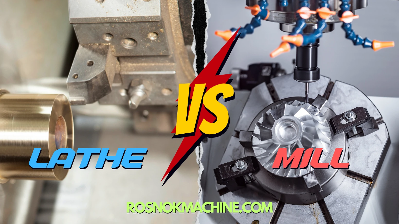
Introduction to Straight Turning
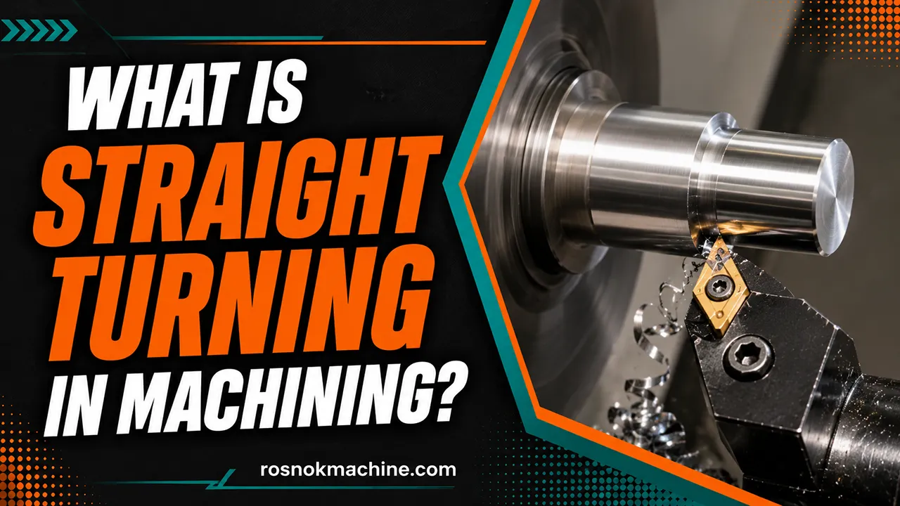
Straight turning is a fundamental lathe operation used to generate a uniform cylindrical surface by removing material along the workpiece’s axial direction. It is characterized by a straight, linear tool path that maintains a constant cutting diameter over the machining length.
In machining workflows, straight turning is used when the primary requirement is geometric consistency along a cylindrical surface. It establishes the basic outer geometry of a workpiece and ensures that the diameter remains stable along the entire cutting zone. This makes it a standard process for producing rotational parts such as shafts and sleeves before additional machining features are introduced.
Within the broader turning process chain, straight turning functions as a primary shaping step focused on external cylindrical accuracy. Its value lies in producing a stable and repeatable base geometry that supports later machining operations without introducing unnecessary complexity in tool movement or surface generation.

Straight Turning Working Principle
Straight turning is based on the relative motion between a rotating workpiece and a single-point cutting tool. The workpiece rotates around its axis while the tool feeds parallel to that axis, maintaining a constant straight tool path along the machining length.
Material removal occurs as the cutting edge continuously engages the rotating surface, shearing off a thin layer of material per revolution. This repeated cutting action generates a uniform reduction in diameter along the workpiece, forming a cylindrical geometry.
The process depends on stable spindle rotation and linear tool feed. Any deviation in rotation concentricity or feed direction directly affects diameter consistency and surface integrity. This makes motion stability the core requirement of straight turning performance.

Straight Turning Tools and Tool Geometry
Straight turning relies exclusively on single-point cutting tools. In modern manufacturing, these typically consist of indexable carbide or coated inserts secured within a rigid tool holder. The tool holder’s primary role is to provide structural stability, absorbing the intense forces generated during the shearing process and keeping the cutting edge perfectly aligned.
The effectiveness of the cutting action is dictated by the insert’s specific geometry:
- Rake Angle: The slope of the tool face that directs the flow of the sheared chip away from the cutting zone.
- Clearance Angle: The angle below the cutting edge designed to prevent the tool’s flank from rubbing against the newly machined surface.
- Nose Radius: The rounded tip of the insert that physically engages the workpiece material.
Under the continuous heat and friction of the machining process, these tools experience inevitable physical degradation. This wear phenomenon primarily manifests as crater wear on the top tool face or flank wear along the cutting edge, which gradually alters the tool’s original geometry.

Materials Suitable for Straight Turning
Straight turning is a versatile process capable of shaping a wide array of industrial materials. However, the basic machining behavior during the shearing process varies significantly depending on the material’s mechanical properties:
- Carbon Steel: Offers predictable machining behavior with stable, continuous chip formation, making it highly responsive to the straight turning process.
- Alloy Steel: The increased toughness and hardness of alloyed metals require higher cutting forces to shear the material and naturally generate more heat.
- Stainless Steel: Notably prone to work-hardening during the cut, requiring consistent tool pressure to prevent the material surface from hardening and resisting the shear force.
- Aluminum Alloys: Highly ductile and easily machinable, this material yields long, continuous chips while requiring comparatively minimal cutting force.
- Cast Iron: Due to its brittle structure, cast iron shears abruptly under the tool, producing short, discontinuous chips or fine, abrasive powder rather than continuous metal ribbons.
Beyond these standard metals, the straight turning process is highly adaptable to other non-ferrous metals (like brass, copper, and titanium) and engineered plastics (such as nylon and PTFE). Ultimately, as long as a material possesses sufficient structural integrity to withstand the rotational shear forces of the cutting tool, it can be effectively shaped using this method.

Straight Turning Process Parameters
The physical execution of straight turning is fundamentally controlled by the precise interaction of three primary machining parameters:
- Cutting Speed: The rate at which the surface of the rotating workpiece moves past the stationary cutting edge. It dictates the intensity of the shearing action and is the primary factor influencing the amount of heat generated at the cutting zone.
- Feed Rate: The linear distance the tool advances along the axial path per one complete revolution of the spindle. The feed rate defines the spacing of the tool marks left on the workpiece, establishing a direct mathematical correlation with the resulting surface finish.
- Depth of Cut: The radial distance the cutting tool penetrates into the workpiece in a single pass. It determines the physical thickness of the material layer being sheared away and is the most significant variable affecting the overall material removal rate.
While each parameter governs a specific aspect of the cut, they operate interdependently. Adjusting one variable instantly alters the physical cutting forces and thermal dynamics of the entire system, meaning the baseline of any straight turning operation relies on carefully balancing these three elements.

Surface Quality in Straight Turning
Surface quality in straight turning refers to the final texture left on the machined cylindrical surface after cutting. It is determined by the interaction between the cutting edge and the workpiece material during continuous material removal.
The most direct contributor to surface texture is the feed motion of the tool. As the tool advances along the axis, it leaves a characteristic pattern of tool marks on the surface, which define the microscopic surface structure.
The tool nose radius also plays a key role in shaping surface continuity. A larger radius generally reduces surface irregularities by smoothing the transition between adjacent cutting paths, while a smaller radius tends to produce more pronounced tool marks.
Material behavior further influences the final surface condition. Ductile materials may show smoother chip flow, while harder or less uniform materials can generate more irregular surface textures due to unstable cutting interaction.
Surface quality in straight turning is therefore the result of combined mechanical interaction between tool geometry, feed motion, and material response during cutting.

Industrial Applications of Straight Turning
Because straight turning excels at generating foundational cylindrical geometries, it is the primary process used to manufacture highly symmetrical, rotational parts across various industries. The most common components produced using this method include:
- Shafts: Both solid and stepped shafts utilized extensively in automotive systems and industrial machinery.
- Pins: Precision mechanical alignment pins required for assembly positioning and load-bearing.
- Bushings and Sleeves: Hollow cylindrical components designed to guide moving parts or reduce friction.
- Mechanical Transmission Components: Cylindrical blanks that serve as the functional foundation for complex power transmission parts.
Beyond producing finished dimensions, straight turning is heavily utilized as a fundamental “roughing stage” process. In this context, it rapidly strips away the bulk exterior material of oversized raw stock, establishing a standardized cylindrical baseline before the part undergoes secondary machining or specialized profiling.

Common Issues in Straight Turning
The intense physical demands of shearing metal during straight turning inevitably expose the process to several observable machining issues. When the interaction between the cutting tool and the workpiece becomes unstable, the following phenomena typically manifest:
- Poor Surface Finish: Appears as visible material tearing, excessive roughness, or unusually deep helical grooves left along the machined cylinder.
- Tool Wear: Presents as the rapid physical degradation, cratering on the insert face, or sudden micro-chipping of the cutting edge.
- Chatter and Vibration Marks: Manifests as distinct, repeating ripple patterns or wavy textures on the workpiece surface, driven by intense mechanical vibration during the cut.
- Dimensional Deviation: Occurs when the final machined cylinder exhibits unintended tapering or fails to hold required diametrical tolerances, directly resulting from the physical deflection of the tool or the workpiece.
- Heat Effects: Appears as thermal distortion of the overall workpiece geometry or localized burning and discoloration on the newly sheared material surface.
Collectively, these phenomena act as direct, observable indicators of mechanical or thermal instabilities occurring during the material removal process.

Conclusion
Straight turning represents one of the most essential and widely used operations in lathe machining, forming the foundation for producing accurate cylindrical parts in modern manufacturing. It may appear simple in tool motion, but its performance depends on a precise balance between cutting mechanics, tool geometry, material response, and process stability. Across the machining process chain, it establishes the primary cylindrical structure that supports all subsequent machining operations, making it a critical step in achieving dimensional consistency and surface reliability in industrial production.
Within this manufacturing context, companies specializing in CNC machine tools play a key role in ensuring process stability and machining precision. Rosnok is positioned in this field as a manufacturer focused on CNC lathes and machining solutions designed for metal processing applications, supporting industrial users with equipment aimed at stable cutting performance and long-term accuracy.