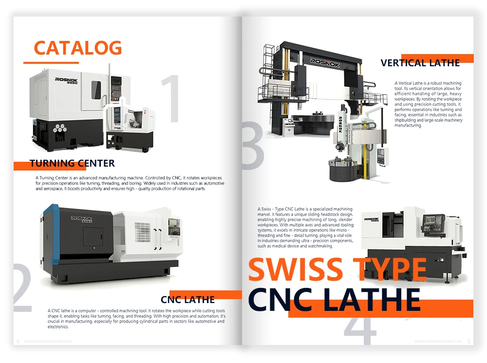
Have you ever wondered how CNC machines follow precise movements with incredible accuracy? How do they know exactly where to cut, how fast to move, and when to stop? What makes one machine more efficient than another, even when performing similar tasks? What role do G Code and M Code play in CNC machining?
G Code is the programming language that controls the movement of CNC machines, guiding tool paths, feed rates, and cutting actions with precision. M Code, on the other hand, handles machine-related functions such as starting or stopping the spindle, activating coolant, and changing tools. Together, they form the essential commands that allow CNC machines to operate efficiently and execute complex machining tasks.
Whether you’re a beginner or looking to refine your programming skills, this guide will walk you through G Code step by step. You’ll learn essential commands, explore real-world applications, and understand how M Code works alongside G Code to control auxiliary functions. Let’s dive in and start mastering G Code and M Code!
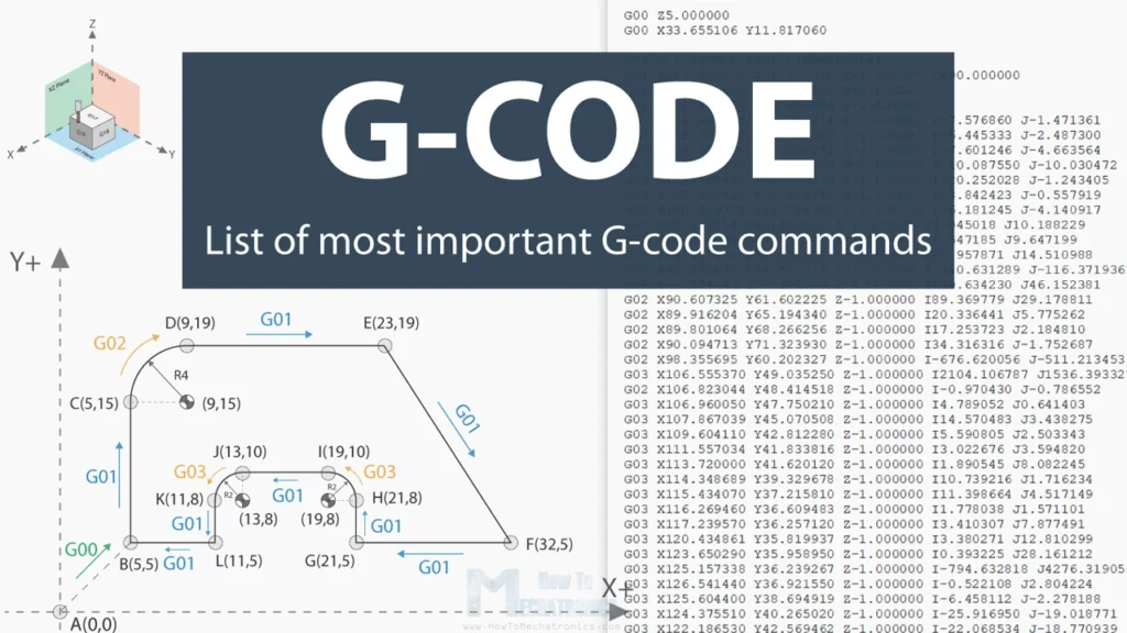
G Code Definition: What is G Code?
What is G Code, and How Does It Control CNC Machines?
G Code (Geometric Code) is the standard language used in CNC programming to control machine movements. It provides precise instructions on how a CNC machine should move, cut, and interact with materials. Whether for milling, turning, drilling, or 3D printing, G Code ensures high accuracy and repeatability in automated machining.
In CNC machining, a G Code file consists of lines of text-based commands that the machine reads and executes step by step. These commands dictate:
- Tool movement (linear, circular, rapid positioning).
- Feed rates and cutting speeds.
- Spindle control and tool selection.
- Cutter compensation and offsets.
With G Code, machinists and programmers can create intricate designs, optimize cutting efficiency, and achieve precision manufacturing without manual intervention.
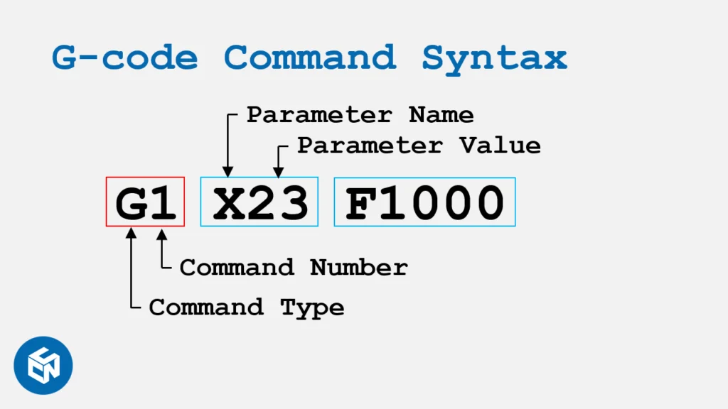
The Structure and Format of a G Code Command
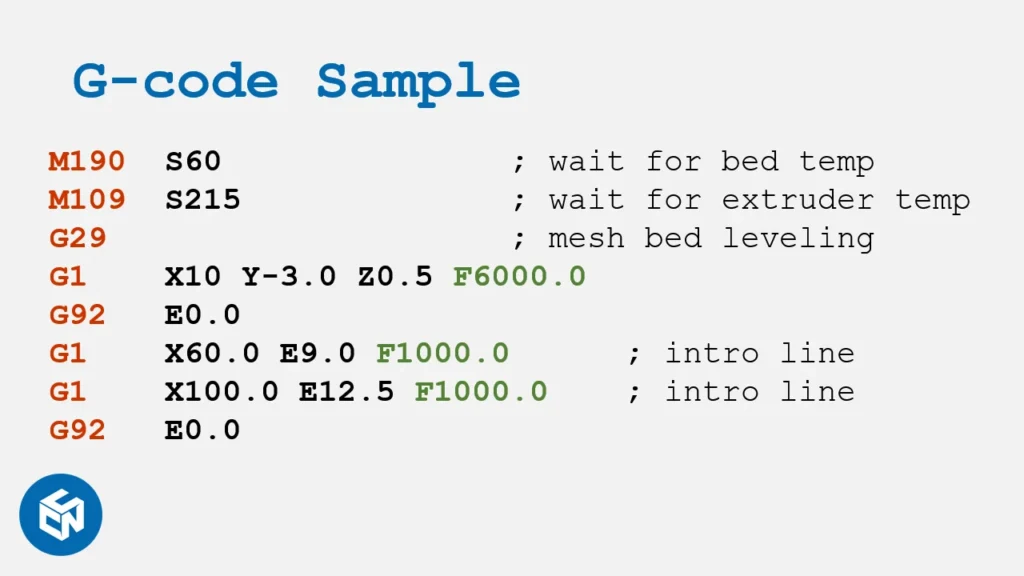
A typical G Code command follows a structured format that includes:
- Letter Prefix: Represents the type of action (e.g., “G” for geometric movements).
- Number Code: Specifies the exact command (e.g., “G01” for linear movement).
- Coordinate Values: Defines movement positions (e.g., “X100 Y50 Z10”).
- Feed Rate and Speed Settings: Determines how fast the tool moves and cuts.
Example G Code Line:
- G01: Move in a straight line.
- X50 Y50: Move to coordinate (50,50).
- F200: Use a feed rate of 200 mm/min.
Absolute vs. Incremental Positioning (G90 vs. G91 G Code)
CNC machines can operate in two positioning modes:
G90 – Absolute Positioning Mode
- All coordinates are referenced from a fixed zero point.
- Example:
Moves to X=100, Y=50 from the machine’s fixed origin.
G91 – Incremental Positioning Mode
- Coordinates are referenced from the current position.
- Example:
Moves 20mm right and 10mm up from the last position.
Cutter Compensation and Offsets (G41 G Code, G42 G Code)
In CNC machining, tools have physical dimensions, meaning the center of the tool might not match the programmed path. Cutter compensation adjusts for this to maintain accurate cutting.
G41 – Cutter Compensation Left
- Offsets the tool left of the programmed path.
- Used when cutting clockwise around a part.
G42 – Cutter Compensation Right
- Offsets the tool right of the programmed path.
- Used when cutting counterclockwise.
G40 – Cancel Cutter Compensation
- Turns off any cutter compensation.
Example of Cutter Compensation in Use:
G41 activates left cutter compensation.
The machine moves to (100,100) while adjusting for the tool radius.
G40 cancels the compensation once cutting is complete.
Mastering G Code is the key to precision CNC machining. By understanding its structure, movement commands, and positioning modes, programmers can optimize machining efficiency, accuracy, and quality.
M Code Definition: What is M Code?
What is M Code, and How Does It Differ from G Code?
While G Code (Geometric Code) controls movement and positioning in CNC machining, M Code (Miscellaneous Code) is responsible for controlling auxiliary machine functions. These commands handle operations that are not directly related to tool movement, such as starting and stopping the spindle, turning coolant on or off, and controlling tool changes.
Unlike G Code, which specifies precise geometric paths, M Code is machine-specific, meaning that different CNC manufacturers may use different M Codes for the same function. However, many standard M Codes are universally recognized.
Key Differences Between G Code and M Code:
| Feature | G Code | M Code |
|---|---|---|
| Purpose | Controls movement and positioning | Controls auxiliary functions |
| Examples | G00 (Rapid Move), G01 (Linear Move) | M03 (Spindle ON), M06 (Tool Change) |
| Focus | Tool paths, cutting actions | Machine control actions |
| Execution Order | Sequential, defines tool movement | Executes system commands |
How M Code is Used to Control Auxiliary Machine Functions
M Codes instruct the CNC machine to perform operations that support machining but are not directly related to cutting paths. Here are some common functions controlled by M Code:
- Spindle Control: Turning the spindle on or off at specified speeds.
- Coolant Activation: Enabling or disabling coolant flow to prevent overheating.
- Tool Changes: Directing the CNC machine to swap out tools automatically.
- Program Execution: Controlling pauses, stops, and resets in a CNC program.
Each M Code command is typically placed on its own line in a CNC program and executed immediately before proceeding to the next command.
The Structure and Syntax of M Code Commands
An M Code command is written as a single letter "M" followed by a numerical value.
Here’s the general structure of an M Code line:
"M" specifies that it’s an M Code.
The [Code] is a number defining the function (e.g., M08 for turning coolant ON).[Optional Parameter] may include tool or spindle details, depending on the command.
Example of an M Code block in a CNC program:
M06 → Changes the tool to Tool 1.
M03 → Starts the spindle at 1500 RPM (Clockwise).
M08 → Turns coolant ON.
M09 → Turns coolant OFF.
M30 → Ends the program and resets the machine.
Why M Code is Essential in CNC Machining
- Automates essential machine operations to reduce manual intervention.
- Enhances machining efficiency by controlling spindle, coolant, and tool changes.
- Works alongside G Code to execute a complete CNC program.
Without M Code, CNC machines would not be able to control basic functions like spindle movement, coolant activation, or program execution, making automation impossible.
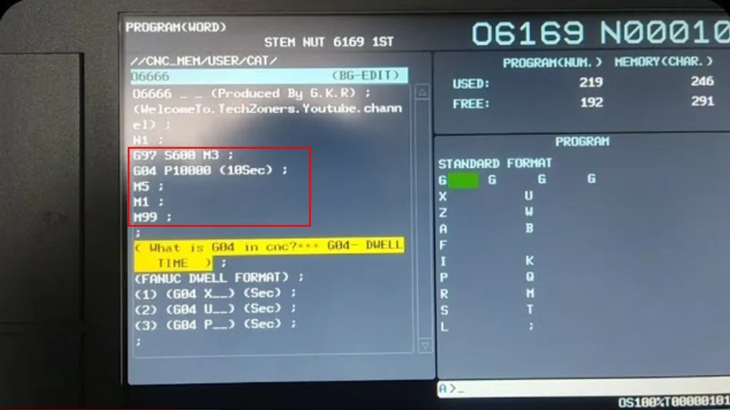
The Importance of G Code and M Code in CNC Machining
Why Are G Code and M Code Essential?
CNC machining is entirely dependent on G Code and M Code to function efficiently. These programming languages bridge the gap between design and execution, converting CAD (Computer-Aided Design) models into precise machine movements.
Without G Code, CNC machines wouldn’t know how to move, cut, drill, or position the tool. Without M Code, machines couldn’t start the spindle, change tools, or apply coolant, making automated manufacturing impossible.
- Precision & Accuracy → G Code ensures tool movement follows precise paths with defined speeds and depths.
- Automation & Efficiency → M Code automates machine functions, reducing manual intervention and human error.
- Consistency & Repeatability → CNC machines execute the same instructions perfectly, ensuring identical results for every batch.
How G Code and M Code Enable Automated Manufacturing
CNC machining is widely used in industries like aerospace, automotive, and medical device manufacturing, where precision and efficiency are critical. G Code and M Code work together to control every aspect of the machining process:
- Design & Programming → Engineers create a CAD model and convert it into G Code using CAM software.
- Tool Path Execution → G Code moves the tool precisely along X, Y, and Z axes to shape materials.
- Machine Control → M Code manages the spindle speed, tool changes, and coolant activation to optimize machining.
- Automated Repeats → CNC programs allow for high-volume production with consistent accuracy.
Real-World Applications of G Code and M Code
Let’s look at how G Code and M Code are applied in different CNC processes:
- Milling → G Code controls tool paths for cutting, while M Code manages spindle and coolant functions.
- Turning (Lathe Operations) → G Code defines cutter positioning, and M Code automates spindle speed and part ejection.
- Drilling & Tapping → G Code directs hole positioning, while M Code ensures proper tool change and depth control.
- 3D Printing → G Code translates digital designs into layered tool paths, while M Code handles filament extrusion and temperature.
Example: How G Code and M Code Work Together
Below is a sample CNC program that combines G Code and M Code to perform a basic machining task:
What This Program Does:
Changes the tool to T2 → M06 T02
Starts the spindle at 1200 RPM → M03 S1200
Moves the tool to (50,50) at feed rate 400 → G01 X50 Y50 F400
Enables coolant during cutting → M08
Executes a clockwise arc move → G02 X100 Y50 I25 J0
Turns coolant off and ends the program → M09, M30
Why Mastering G Code and M Code Matters
- Maximizing CNC Machine Potential → Skilled programmers can write efficient, optimized G Code for faster cycle times.
- Reducing Errors & Waste → Proper M Code usage prevents spindle damage, overheating, and tool misalignment.
- Expanding Career Opportunities → Engineers, machinists, and manufacturers who master G Code & M Code are in high demand.
Common G Code Commands and Their Functions Listing
G Code is the foundation of CNC programming, allowing machinists to control tool movement, cutting speed, and positioning with precision. Each G Code command serves a specific purpose, making it essential to understand how they work.
In this section, we’ll explore the most commonly used G Codes, their functions, and how they apply in real-world CNC machining.
1. Movement Commands: Positioning and Motion Control
Movement commands are essential for controlling tool movement and positioning in CNC machines. These commands define how the tool moves, whether in a straight line, a rapid motion, or along a curved path.
G00 – Rapid Positioning (Fast Movement)
The G00 command moves the tool at the machine’s maximum speed to a specific position. It is used when no cutting is required—for example, moving the tool to a new location before machining starts.
- Function → Moves the tool quickly from one position to another.
- Use Case → Positioning the tool before starting a cut.
Example: Move the tool to (X100, Y50, Z20) at maximum speed
G01 – Linear Interpolation (Straight Line Cutting)
The G01 command moves the tool in a straight line at a controlled feed rate. It is used for precise cutting operations.
- Function → Moves the tool in a straight line while cutting.
- Use Case → Performing straight-line cuts in materials like aluminum or steel.
Example: Move the tool to (X200, Y100) at a feed rate of 500 mm/min
G02 – Clockwise Circular Interpolation (Arc Cutting)
The G02 command instructs the machine to move in a circular arc in a clockwise direction.
- Function → Creates a clockwise arc from the start position.
- Use Case → Machining circular pockets, arcs, and curved surfaces.
Example: Cut an arc with a radius of 25 from the current position to (X150, Y100)
G03 – Counterclockwise Circular Interpolation
The G03 command works the same as G02, but it moves the tool counterclockwise instead.
- Function → Moves the tool in a counterclockwise arc.
- Use Case → Cutting arcs that need to be in the opposite direction.
Example: Move to (X100, Y50) in a counterclockwise motion with a radius of 30
2. Spindle and Feed Rate Control Commands
Controlling the spindle speed and feed rate is critical for achieving optimal cutting conditions. These commands allow machinists to adjust cutting speeds for different materials and machining operations.
G96 – Constant Surface Speed (CSS)
The G96 command keeps the cutting speed constant by automatically adjusting the spindle RPM based on the tool’s distance from the center.
- Function → Ensures a consistent cutting speed by changing spindle RPM.
- Use Case → Used in lathe operations to maintain an optimal cutting speed.
Example: Set a constant surface speed of 200 m/min
G97 – Cancel Constant Surface Speed (Fixed RPM Mode)
The G97 command disables constant surface speed mode and sets the spindle to a fixed RPM.
- Function → Runs the spindle at a constant RPM.
- Use Case → Used when constant speed control is not necessary.
Example: Set spindle speed to 1500 RPM
G94 – Feed Per Minute Mode
The G94 command sets the feed rate in mm/min or inches/min.
- Function → Defines how fast the tool moves per unit of time.
- Use Case → Used in milling operations.
Example: Set a feed rate of 400 mm/min
G95 – Feed Per Revolution Mode
The G95 command sets the feed rate based on spindle revolutions (mm/rev or in/rev).
- Function → Defines the feed per revolution, rather than per minute.
- Use Case → Used in lathe turning operations where feed depends on spindle speed.
Example: Set a feed rate of 0.2 mm per revolution
3. Drilling and Cycle Commands
Drilling and cycle commands allow CNC machines to automate hole-making operations such as drilling, tapping, and deep-hole boring. These commands ensure precision, repeatability, and efficiency in machining processes, reducing manual intervention and optimizing production speed.

G81 – Simple Drilling Cycle
The G81 command is used for basic drilling. The machine will move to the specified position, drill down, and retract.
- Function → Drills a hole without pecking.
- Use Case → Used for standard drilling operations.
Example: Drill a hole at (X100, Y50) with a depth of -10mm
G83 – Peck Drilling Cycle
The G83 command is used for deep hole drilling, where the tool retracts between drilling to remove chips.
Function → Drills in steps, retracting to clear chips.
Use Case → Used for deep drilling where chip removal is important.
Example: Drill in increments of 3 mm at (X50, Y50)
4. Machine Coordinate System and Offsets
Machine coordinate system and offset commands define reference points and work offsets, allowing CNC machines to accurately position tools relative to the workpiece. These commands help machinists set up multiple jobs, improve precision, and streamline machining operations across different setups.
G54 – Work Offset Coordinate System
The G54 command defines the origin (zero point) of the workpiece.
- Function → Assigns a specific work offset for the CNC machine.
- Use Case → Used to set up different workpieces on the same machine.
Example: Set the work offset at X50, Y100, Z10
G28 – Return to Machine Home Position
The G28 command moves the tool to the machine’s reference (home) position.
- Function → Sends the tool back to its home position safely.
- Use Case → Used after completing a program to reset the tool position.
Example: Move the tool to machine home
Mastering these common G Codes is crucial for efficient and precise CNC machining. Understanding when and how to use them will improve your programming skills, reduce errors, and optimize machining operations.
Common M Code Commands and Their Functions Listing
M Code (Miscellaneous Code) controls non-movement functions in CNC machining, such as spindle activation, tool changes, coolant control, and program stops. These commands work alongside G Code to fully automate CNC operations, ensuring machines run efficiently.
Understanding M Codes is essential for machinists and programmers to execute complex machining processes with precision and reliability.
1. Spindle Control Commands
Spindle control commands manage the rotation of the cutting tool, defining its speed and direction. These commands are essential for adjusting spindle RPM, starting or stopping rotation, and ensuring the right cutting conditions for different materials.
M03 – Start Spindle Clockwise
The M03 command starts the spindle rotating clockwise at a specified speed (RPM).
- Function → Turns the spindle ON (Clockwise).
- Use Case → Used for milling and drilling operations requiring standard rotation.
Example: Start spindle clockwise at 1200 RPM
M04 – Start Spindle Counterclockwise
The M04 command starts the spindle rotating counterclockwise at a specified RPM.
- Function → Turns the spindle ON (Counterclockwise).
- Use Case → Used for left-hand threading and reverse cutting tools.
Example: Start spindle counterclockwise at 800 RPM
M05 – Stop Spindle
The M05 command stops the spindle completely.
- Function → Stops spindle rotation.
- Use Case → Used after a cutting cycle to pause machining operations safely.
Example: Stop the spindle
2. Tool Change Commands
Automatic tool changers (ATC) allow CNC machines to switch tools during a machining process without manual intervention. These commands ensure smooth transitions between cutting tools, increasing efficiency and reducing downtime.
M06 – Tool Change
The M06 command changes the current tool to a new tool specified in the program.
- Function → Switches to the next tool automatically.
- Use Case → Used in automatic tool changers (ATC) for multi-step machining.
Example: Change to Tool 5
3. Coolant Control Commands
Coolant plays a crucial role in CNC machining by reducing heat, preventing tool wear, and improving cutting performance. Coolant control commands enable machinists to turn coolant flow on or off as needed.
M08 – Coolant ON
The M08 command turns the coolant system ON, helping reduce heat and improve tool life.
Function → Activates coolant flow.
Use Case → Used when cutting materials that generate heat, such as aluminum and steel.
Example: Turn coolant ON
M09 – Coolant OFF
The M09 command stops coolant flow.
Function → Disables coolant to prevent unnecessary waste.
Use Case → Used at the end of a cutting operation.
Example: Turn coolant OFF
4. Program Execution and Control Commands
Program execution commands control the start, pause, and stop of CNC machining cycles. These commands ensure proper sequencing and allow for safe operator intervention when needed.
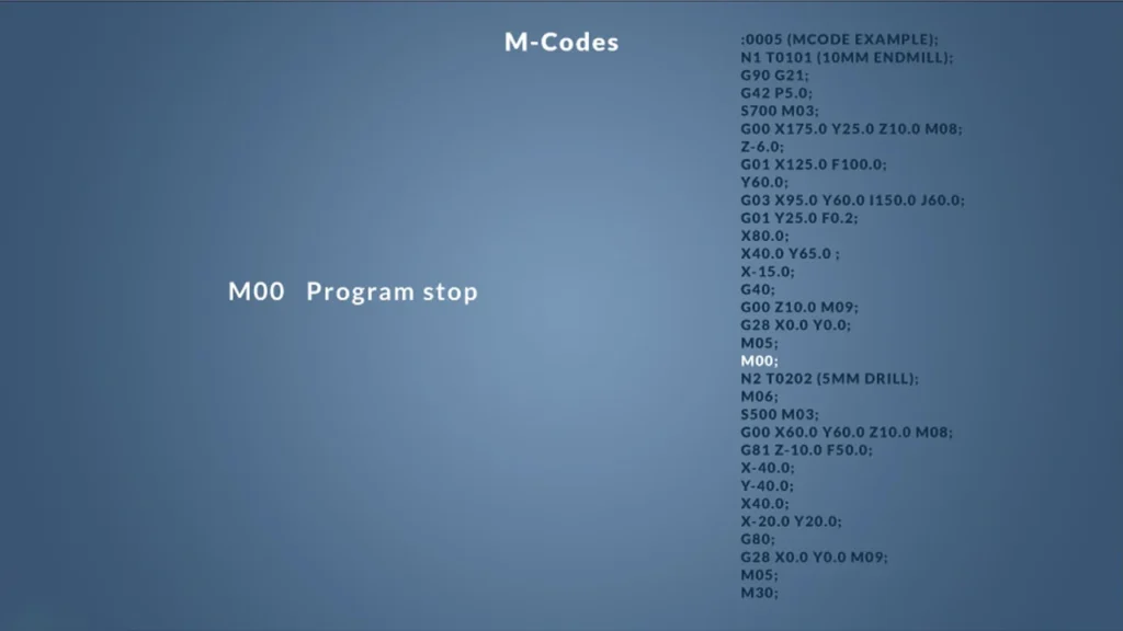
M00 – Program Stop (Pause)
The M00 command stops the program until the operator manually resumes it.
- Function → Pauses the program at a defined point.
- Use Case → Used when manual inspection or operator input is needed.
Example: Pause the program
M30 – End Program and Reset
The M30 command stops the program, resets the machine, and prepares for a new cycle.
Function → Ends the CNC program and resets the machine.
Use Case → Used at the completion of a machining cycle.
Example: End the program and reset
5. Example of an M Code Block in a CNC Program
The following example combines multiple M Codes to show how they work together in a CNC program:
What This Program Does:
- Changes the tool to T2 →
M06 T02 - Starts the spindle at 1200 RPM →
M03 S1200 - Moves the tool to (50,50) at feed rate 400 →
G01 X50 Y50 F400 - Enables coolant during cutting →
M08 - Executes a clockwise arc move →
G02 X100 Y50 I25 J0 - Turns coolant off and ends the program →
M09, M30
Mastering M Code commands is just as important as learning G Code. These commands allow CNC machines to control essential functions like spindle speed, coolant flow, and tool changes, making machining safer, faster, and more efficient.
How to Read and Write G Code and M Code
Understanding how to read and write G Code and M Code is crucial for mastering CNC programming. Whether you’re a beginner or an experienced machinist, knowing how to interpret and create CNC programs allows you to modify machining operations, troubleshoot errors, and optimize production efficiency.
This section will break down the structure of a CNC program, explain how commands work together, and provide step-by-step guidance on writing G Code and M Code from scratch.

1. Understanding the Structure of a G Code Program
A CNC program consists of multiple lines of G Code and M Code, which the machine reads line by line to execute operations. Each line is called a block and typically follows this structure:
Block Format:
Explanation:
- N10 → Block Number (Optional, used for reference)
- G01 → Linear movement command
- X50 Y50 → Move to coordinates (50,50)
- F200 → Feed rate of 200 mm/min
- M08 → Turn coolant ON
Tip: Block numbers (N10, N20, etc.) are optional but help organize large programs.
2. Writing Your First G Code Program
Step 1: Define the Program Start and Safety Commands
Every CNC program begins with a safety setup to ensure proper operation.
What This Does:
- O1000 → Program number
- G21 → Use millimeters as units
- G17 → Select XY plane
- G90 → Absolute positioning mode
- M06 T01 → Select Tool 1
- M03 S1500 → Start spindle clockwise at 1500 RPM
- M08 → Turn coolant ON
Step 2: Add Machining Operations (Movements and Cutting)
This section tells the CNC machine how to move and cut material.
What This Does:
- G00 → Rapid positioning to (0,0)
- G01 → Move to (50,50) at 300 mm/min
- G02 → Clockwise arc move to (100,50)
- G03 → Counterclockwise arc move to (150,50)
Tip: Use G02/G03 for arcs and G01 for straight movements.
Step 3: End the Program Safely
Every CNC program must end properly to reset the machine.
What This Does:
- G00 X0 Y0 → Return tool to the home position
- M09 → Turn coolant OFF
- M05 → Stop spindle rotation
- M30 → End program and reset
Tip: Always include M30 to ensure the CNC machine returns to a safe state after execution.
3. How to Read an Existing G Code Program
If you receive a pre-written G Code file, follow these steps to read and understand it:
Step 1: Identify the Key Sections
A CNC program usually has three main parts:
- Setup Section – Defines tools, units, spindle speed, and safety commands.
- Machining Section – Contains movement and cutting commands.
- Ending Section – Turns off coolant, stops the spindle, and resets the machine.
Example: Full Program Breakdown
How to Read It:
- First, locate the setup section (Tool Change, Spindle Speed, Units).
- Identify movement commands (G00, G01, G02, G03).
- Look for auxiliary functions (Coolant, Spindle ON/OFF).
- Find the ending commands (M05, M09, M30).
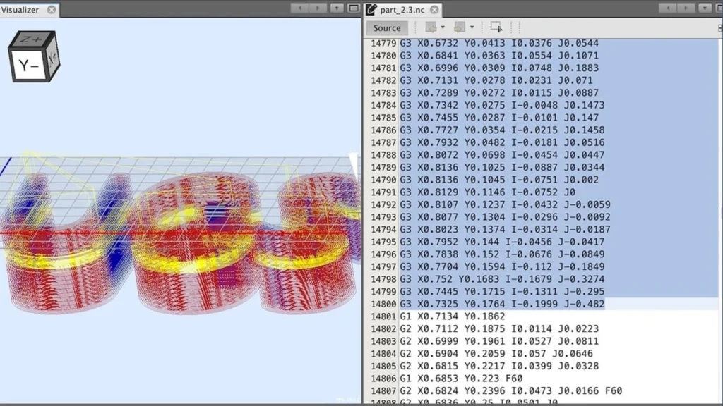
4. Using G Code Simulators and Editors
To practice without running a real CNC machine, use G Code simulators and editors.
Popular G Code Simulators:
- NC Viewer – Free online tool for visualizing toolpaths.
- G-Wizard Editor – Advanced editor with error detection.
- CNC Simulator Pro – Full-featured simulation software.
Tip: Use a simulator before running the program on an actual CNC machine to avoid costly errors.
Learning how to read and write G Code and M Code is a fundamental skill for CNC machinists. By understanding program structure, movement commands, and safety protocols, you can confidently write, modify, and troubleshoot CNC programs.
Practical Examples of G Code and M Code in Action
Understanding G Code and M Code is one thing, but seeing them in real-world applications is what truly brings them to life. In this section, we will explore practical examples of G Code and M Code in different CNC machining operations, including milling, lathe operations, and automation tasks.
These examples will help beginners see how CNC programs are structured and how different commands work together to execute precise machining tasks.
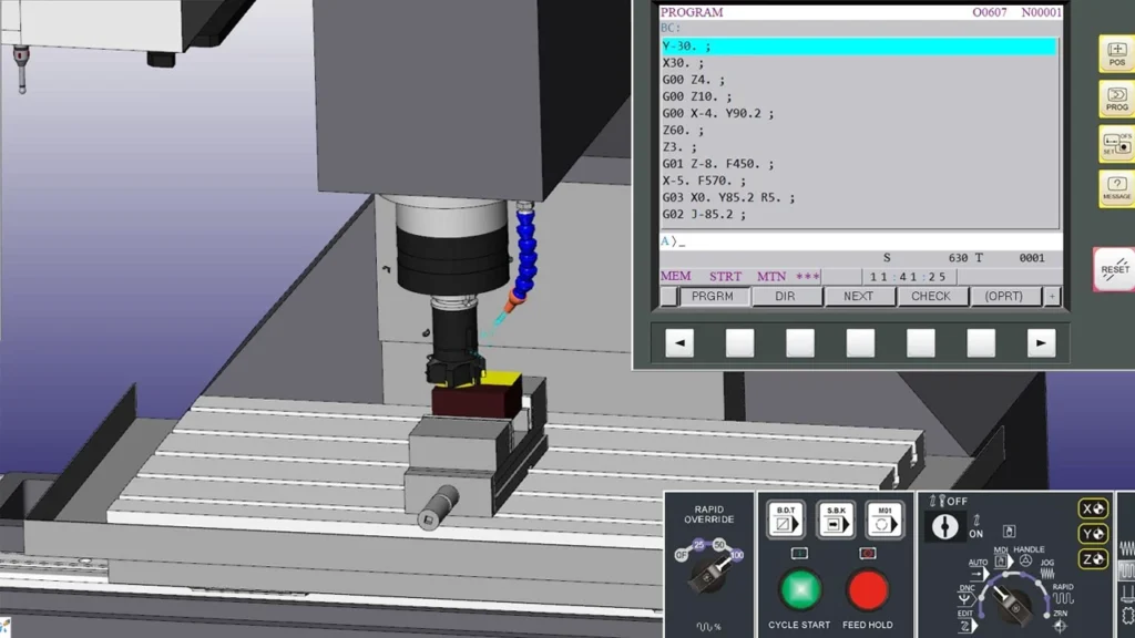
1. G Code for Milling: Cutting a Simple Square
Milling operations require precise tool movement to shape materials accurately. Below is a G Code program to cut a 50mm x 50mm square with a feed rate of 200 mm/min.
Example: Cutting a 50mm x 50mm Square
What This Program Does:
- Sets the machine’s unit to millimeters and selects absolute positioning →
G21 G90 - Starts the spindle at 1200 RPM and activates coolant →
M03 S1200, M08 - Moves the tool to the start position at (0,0) →
G00 X0 Y0 Z10 - Cuts a 50mm x 50mm square by moving in straight lines →
G01 X50 Y0, G01 X50 Y50, etc. - Turns off coolant, stops spindle, and ends the program →
M09, M05, M30
2. G Code for Lathe: Turning a Cylindrical Part
CNC lathes use G Code and M Code to shape cylindrical parts by removing material in layers. The following example demonstrates a simple turning operation that cuts a cylinder 30mm in diameter.
Example: Lathe Turning Operation
What This Program Does:
- Sets units to millimeters and selects the ZX plane for lathe operations →
G21 G18 G90 - Starts spindle at 1000 RPM and enables coolant →
M03 S1000, M08 - Moves the tool to the starting position at (X35, Z5) →
G00 X35 Z5 - Cuts a cylindrical shape by moving in the Z direction →
G01 Z-40, G01 X30 - Retracts the tool and stops the spindle →
G00 X35 Z5, M05
3. M Code in Real Applications: Tool Changes, Coolant, and Spindle Control
M Code commands are crucial for machine control beyond movement. Let’s look at an example where M Code manages tool changes, coolant, and spindle operations.
Example: Tool Change and Coolant Control in a Milling Operation
Key M Code Functions in This Program:
- Tool Change to Tool 3 →
M06 T03 - Start spindle at 800 RPM (Clockwise) →
M03 S800 - Coolant ON during cutting →
M08 - Coolant OFF and Spindle Stop after operation →
M09, M05
4. How G Code and M Code Work Together in a Complete CNC Program
In real-world CNC machining, G Code and M Code work together seamlessly to execute a complete machining cycle.
Here’s a full example program combining milling, tool changes, and coolant control:
What This Full Program Demonstrates:
- Tool change from T01 to T02 →
M06 T01, M06 T02 - Two different spindle speeds →
M03 S1000, M03 S800 - Cutting multiple sections in one program →
G01 X60 Y10,G01 X70 Y20 - Coolant control at different stages →
M08, M09
These practical examples show how G Code and M Code work together to execute milling, turning, and automation operations. By studying these examples, machinists can write, modify, and troubleshoot CNC programs confidently.
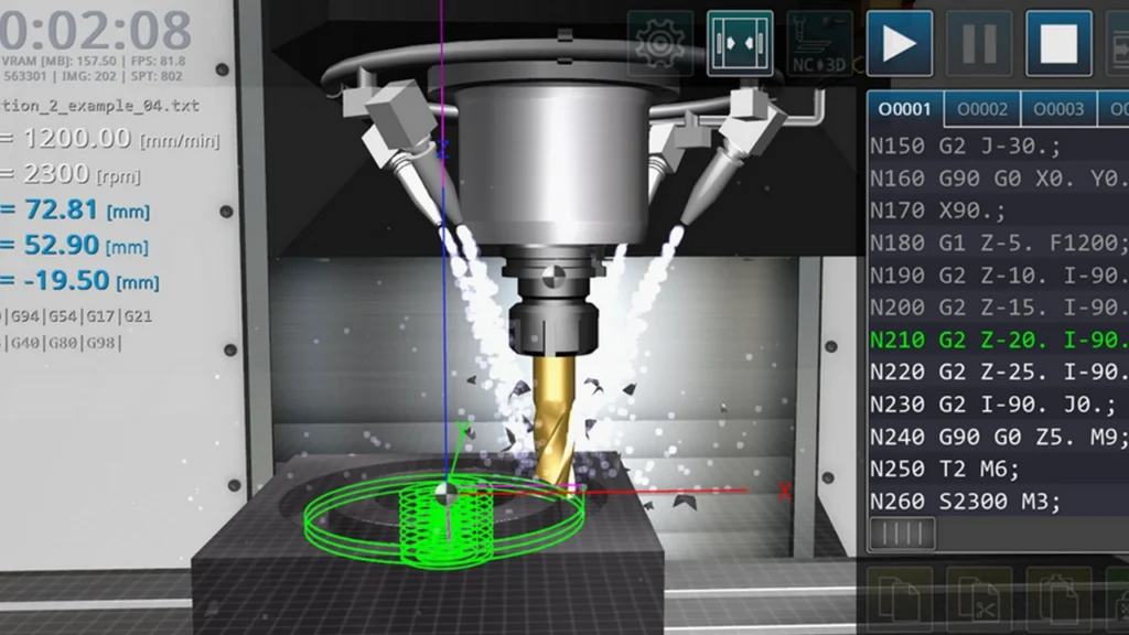
Troubleshooting Common G Code and M Code Errors
Even experienced CNC machinists encounter errors in G Code and M Code programming. Understanding common mistakes, error messages, and debugging techniques is crucial for avoiding downtime, reducing material waste, and improving efficiency.
In this section, we’ll go over the most common CNC programming errors, how to identify them, and step-by-step solutions to fix them.
Common G Code Errors and How to Fix Them
G Code controls tool movement, so errors in G Code can lead to incorrect cutting paths, tool crashes, or workpiece misalignment. Below are common G Code mistakes and how to fix them.
1. Error: Missing or Incorrect Work Coordinate System (G54, G55, etc.)
Issue: If the work offset (G54, G55, etc.) is missing, the machine might reference the wrong zero point, leading to incorrect cutting positions.
Fix: Always define the correct work coordinate system at the beginning of your program.
Incorrect Code (Missing G54)
Correct Code (Including G54)
2. Error: Improper Feed Rate (F Code Missing or Incorrect)
Issue: If no feed rate (F value) is set, the CNC machine might default to an unsafe speed or fail to move.
Fix: Always include a feed rate (F value) before executing a movement command.
Incorrect Code (Missing Feed Rate)
Correct Code (With Feed Rate)
3. Error: Using Absolute (G90) and Incremental (G91) Positioning Incorrectly
Issue: If you switch between absolute and incremental positioning modes without realizing it, the tool might move incorrectly, causing crashes.
Fix: Always double-check whether G90 (absolute) or G91 (incremental) is active.
Incorrect Code (Switching Without Warning)
Correct Code (Proper Transition)
Common M Code Errors and How to Fix Them
M Code controls non-movement functions like spindle activation, tool changes, and coolant. If errors occur, they can cause machine malfunctions or inefficiencies.
4. Error: Spindle Won’t Start (M03 / M04 Missing S Value)
Issue: The spindle won’t start if an RPM value (S value) is missing.
Fix: Always define a spindle speed before running M03 or M04.
Incorrect Code (No Speed Defined)
Correct Code (With Speed Defined)
5. Error: Coolant Doesn’t Turn Off (Forgetting M09 Command)
Issue: If the program doesn’t include M09, the coolant might continue running, wasting coolant and causing unnecessary machine wear.
Fix: Always turn coolant OFF when it is no longer needed.
Incorrect Code (Missing Coolant OFF Command)
Correct Code (Includes Coolant OFF Command)
6. Error: Tool Change Failure (Forgetting M06 or T Code)
Issue: If M06 (tool change command) is missing or not paired with a tool number (T value), the machine won’t switch tools correctly.
Fix: Always include M06 and a tool number (T value).
Incorrect Code (Missing Tool Number)
Correct Code (Proper Tool Change)
How to Debug G Code and M Code Errors
If an error occurs, follow these troubleshooting steps to identify and fix the problem.
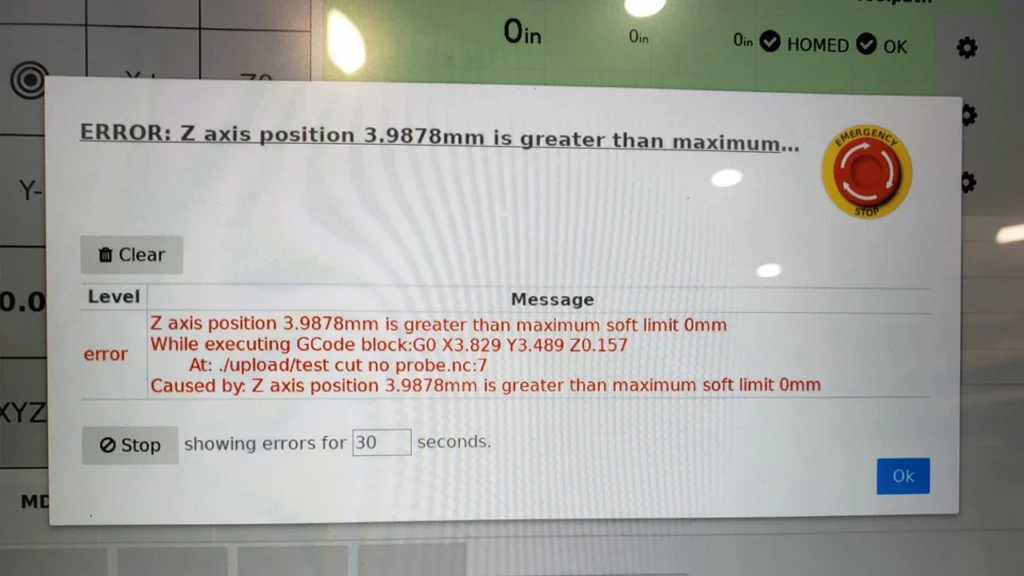
Step 1: Read the CNC Machine Error Message
Most CNC controllers will display an error message when something goes wrong. Common error messages include:
- “Invalid G Code” → Check if the G Code exists for your machine.
- “Spindle Not Started” → Ensure you used
M03 SxxxxorM04 Sxxxx. - “Tool Not Found” → Ensure
M06 Txxmatches an available tool.
Step 2: Check for Missing Commands
Many errors occur because required commands are missing. Always check for:
- Work Offset (G54, G55, etc.)
- Feed Rate (Fxxxx)
- Spindle Speed (Sxxxx) before M03/M04
- Coolant OFF (M09) before ending the program
Step 3: Run a G Code Simulator Before Machining
Before running a program on a real machine, test it in a G Code simulator to visualize the toolpath and catch errors early.
Popular CNC Simulators:
- NC Viewer (Online tool for visualizing G Code)
- G-Wizard Editor (Checks for errors and suggests optimizations)
- CNC Simulator Pro (Full-featured G Code simulator)
Step 5: Use a Step-by-Step Approach to Debugging
If a program fails mid-operation, follow these steps:
- Stop the program immediately if something seems wrong.
- Check the last executed command to find the issue.
- Manually test commands one at a time.
- Compare against a working program to identify missing elements.
Mistakes in G Code and M Code can lead to machine crashes, wasted materials, and production delays. By learning to identify common errors and troubleshoot effectively, CNC machinists can keep their machines running smoothly and safely.
Optimizing CNC Programs with G Code and M Code
Writing efficient CNC programs can significantly reduce cycle time, improve machining accuracy, and extend tool life. By optimizing G Code and M Code, machinists can enhance productivity while minimizing material waste and wear on CNC machines.
In this section, we’ll cover the best practices for writing optimized G Code programs, including reducing unnecessary movements, using loops and subprograms, and improving tool paths for better efficiency.
Best Practices for Writing Efficient G Code
Optimizing G Code starts with eliminating redundant commands and structuring code logically. Below are some essential tips:
1. Reduce Unnecessary Rapid Movements (G00)
Problem: Excessive G00 rapid moves can increase non-cutting time.
Solution: Minimize unnecessary tool repositioning and use direct paths between cuts.
Inefficient Code (Unnecessary Moves)
Optimized Code (Direct Movements)
Why It’s Better?
- Eliminates unnecessary rapid moves
- Combines cutting and positioning in one sequence
2. Use Incremental Positioning (G91) for Repetitive Moves
Problem: Absolute positioning (G90) requires specifying full coordinates for every move, increasing complexity.
Solution: Use incremental positioning (G91) for repetitive patterns like hole drilling or slot cutting.
Inefficient Code (Absolute Positioning for Each Hole)
Optimized Code (Incremental Positioning for Hole Pattern)
Why It’s Better?
- Uses relative movements instead of manually coding each position
- Simplifies programming for patterns like drilling, tapping, and milling
3. Use Subprograms (M98) for Repeated Operations
Problem: Duplicating code for repeated machining operations leads to longer programs and higher chances of errors.
Solution: Use subprograms (M98) to execute repeated sequences.
Inefficient Code (Repeating the Same Path Multiple Times)
Optimized Code (Using Subprogram for Repeated Cuts)
Why It’s Better?
- Shorter, cleaner program
- Easy to modify repeated operations without rewriting code
Reducing Cycle Time with Toolpath Optimization
4. Minimize Tool Changes (Group Operations by Tool)
Problem: Frequent tool changes (M06) increase cycle time.
Solution: Group operations that use the same tool together.
Inefficient Code (Multiple Tool Changes)
Optimized Code (Grouped by Tool)
Why It’s Better?
- Reduces unnecessary tool changes
- Minimizes machine downtime
5. Use Constant Cutting Speed (G96) for Lathe Operations
Problem: Fixed RPM (G97) may cause inconsistent surface speeds when cutting a workpiece of varying diameters.
Solution: Use constant surface speed (G96) to maintain optimal cutting speed across different diameters.
Inefficient Code (Fixed Spindle Speed – G97)
Optimized Code (Constant Surface Speed – G96)
Why It’s Better?
- Keeps cutting speed constant as the workpiece diameter changes
- Improves tool life and surface finish
Choosing the Right G Code Commands for Efficiency
6. Use Cutter Compensation (G41/G42) to Avoid Extra Programming
Problem: Without cutter compensation, programmers need to manually calculate offsets for tool diameter, making the code more complex.
Solution: Use G41 (Left Compensation) or G42 (Right Compensation) to let the machine automatically adjust for the tool size.
Inefficient Code (Manual Offset Calculation Required)
Optimized Code (Using Cutter Compensation – G41/G42)
Why It’s Better?
- Automatically adjusts for tool diameter
- Simplifies programming for different tool sizes
Optimizing G Code and M Code can significantly improve machining efficiency, reduce cycle times, and increase tool life. By following these best practices—eliminating unnecessary movements, using loops/subprograms, optimizing tool paths, and leveraging cutter compensation—machinists can write smarter, faster CNC programs.
Conclusion and Next Steps in CNC Programming
CNC machining relies on G Code and M Code to control every aspect of the manufacturing process—from tool movement to spindle speed, coolant activation, and program execution. Mastering these programming languages is essential for anyone working in CNC machining, whether you’re a beginner or an experienced machinist.
This guide has covered everything from basic G and M Code commands to advanced optimization techniques, helping you build a solid foundation in CNC programming.
Key Takeaways from This Guide
Understanding G Code and M Code
- G Code (geometric instructions) controls tool movement (e.g.,
G00,G01,G02,G03). - M Code (miscellaneous commands) controls machine functions (e.g.,
M03for spindle ON,M06for tool change).
How G and M Code Work Together
- G Code moves the tool, while M Code controls machine operations.
- Example: A milling operation may include
G01(linear move) andM08(coolant ON) in the same sequence.
Writing and Optimizing CNC Programs
- Use absolute (
G90) and incremental (G91) positioning wisely. - Optimize tool paths with subprograms (
M98), cutter compensation (G41/G42), and constant surface speed (G96). - Reduce cycle time by grouping tool changes and eliminating unnecessary rapid moves (
G00).
Troubleshooting Common Errors
- Missing feed rate (
Fxxx) → Machine won’t move properly. - Spindle not starting (
M03 Sxxxxmissing) → Always define a spindle speed. - Tool change issues (
M06 Txxmissing) → Ensure each tool command is properly defined.
Next Steps for Advancing in CNC Programming
Now that you understand the fundamentals of G Code and M Code, here are recommended next steps to deepen your CNC programming skills.
1. Practice Writing and Running G Code
- Start by writing simple programs and testing them on a CNC simulator.
- Experiment with different cutting speeds, tool paths, and cycle optimizations.
- Try modifying an existing CNC program to customize it for different machining tasks.
2. Use G Code Simulators and Software
Recommended G Code Editors & Simulators:
- NC Viewer → Online tool for viewing tool paths and debugging code.
- G-Wizard Editor → Checks for programming errors and suggests optimizations.
- CNC Simulator Pro → Full-featured simulation software for testing programs before machining.
3. Learn Advanced CNC Programming Techniques
To take your CNC skills to the next level, study advanced programming methods such as:
- Macro Programming (Using Variables & Loops) → Automate repetitive machining tasks with
#variables. - Parametric Programming → Use formulas to make programs adaptable for different part sizes.
- High-Speed Machining (HSM) Techniques → Optimize feed rates and tool paths for maximum efficiency.
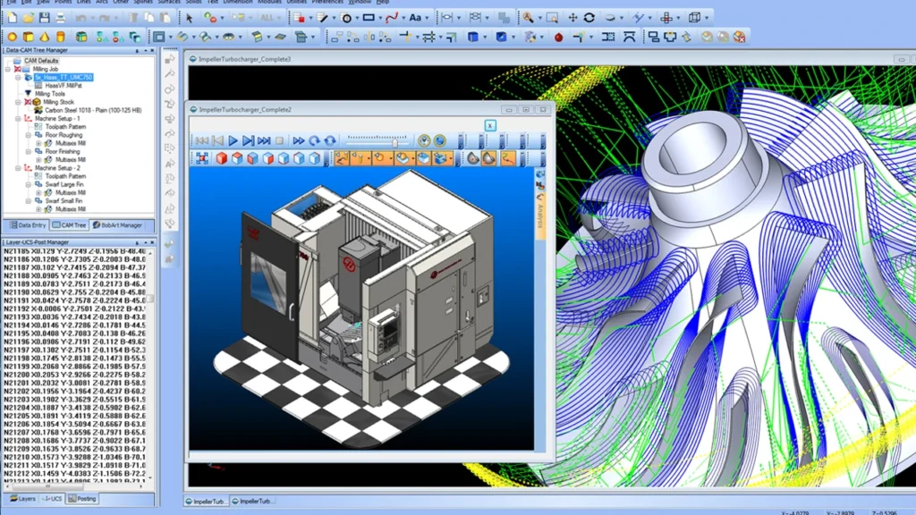
4. Explore CAD/CAM Software for CNC Automation
Instead of manually writing G Code, CAM software can generate optimized G Code automatically.
Popular CNC Software for Automation:
- Fusion 360 → 3D modeling and CAM software with built-in CNC toolpath generation.
- Mastercam → Advanced CAM software for 2D and 3D machining.
- SolidCAM → Works inside SolidWorks to generate efficient tool paths.
5. Stay Updated and Keep Learning
CNC technology is constantly evolving! Stay ahead by learning from industry experts and communities.
Resources for CNC Learning:
- CNC Training Courses → Look for online courses on platforms like Udemy, LinkedIn Learning, and Coursera.
- Industry Forums → Join CNCZone, Practical Machinist, or Autodesk CAM forums for troubleshooting and advice.
- YouTube Channels → Watch CNC tutorials and case studies from real-world machinists.
Final Thoughts: Your Path to CNC Mastery
Mastering G Code and M Code is a crucial step toward becoming a skilled CNC machinist or programmer. By learning how to write, read, and optimize CNC programs, you can:
- Increase machining efficiency and productivity
- Reduce programming errors and downtime
- Improve part quality and consistency
- Advance in your career as a CNC specialist
Whether you’re a beginner learning your first CNC commands or an advanced machinist refining your programming techniques, continuous practice and learning will help you become a true expert in CNC machining.
Now it’s time to apply your knowledge—start writing, testing, and optimizing your CNC programs!
FAQ: G Code and M Code
Is G Code programming still relevant with modern CAM software?
Yes. CAM software generates G Code automatically, but understanding G Code is essential for troubleshooting, optimizing programs, and making manual adjustments. Skilled programmers often fine-tune CAM-generated G Code for better performance.
Can G Code and M Code be used on any CNC machine?
Most CNC machines use G Code and M Code, but implementations can vary between machine brands and controllers. Always refer to the machine’s programming manual to understand supported codes and syntax.
Are G Code and M Code the same on different CNC brands?
No. While many G Code and M Code commands are standardized, variations exist between CNC brands and controllers. Always check the machine’s programming manual for supported codes and specific implementations.
What is the difference between open-loop and closed-loop CNC systems?
Open-loop CNC systems send movement commands to motors but do not check if the motion was completed accurately. They are simpler and cheaper but less precise. Closed-loop systems include feedback devices (like encoders) that report actual position back to the controller. This feedback allows the system to correct any deviation in real time, ensuring higher accuracy, better repeatability, and more reliable machining—especially important for tight-tolerance parts or multi-axis operations.
Do CNC machines need coding knowledge to operate?
Not necessarily. Most modern CNC machines use user-friendly interfaces and rely on CAM software to generate G-code automatically from CAD models. Operators typically load the program, adjust parameters, and monitor the process—without writing code manually. However, understanding basic G-code helps in troubleshooting and optimization. Advanced users or programmers may write or edit code directly, but beginners can operate CNC machines effectively without deep coding knowledge.
How do tool offsets work in CNC programming?
Tool offsets tell the CNC machine where the tip of the cutting tool is relative to a fixed reference point. Each tool is slightly different in length or diameter, so the machine needs this information to position the tool accurately.
During programming, the operator assigns each tool a number and offset value. These offsets are stored in the machine’s control system and automatically applied during tool changes. Without proper offsets, even a perfect G-code program will produce incorrect results because the machine doesn’t know the real position of the tool. Offsets ensure consistent depth, alignment, and accuracy across tools.


