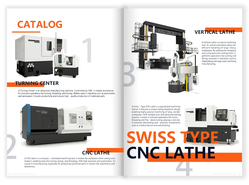
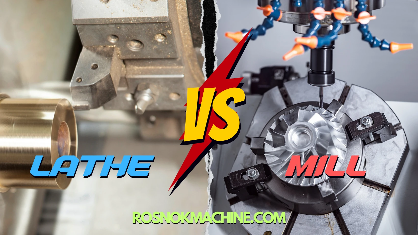
Have you ever wondered what the different types of turning operations are?Confused by the different types of turning operations and when to use each one? Are you unsure which turning operation best suits your part design?
There are 12 widely used turning operations in machining. These include straight turning to reduce diameter, taper turning for sloped surfaces, contour turning for irregular curves, and facing to machine flat ends. Parting-off separates finished pieces, grooving cuts recesses, threading forms screw profiles, drilling creates holes, and boring enlarges them. Knurling adds textured grips, polygon turning produces non-circular shapes, and eccentric turning machines off-center features. Each method matches specific geometries, dimensions, or functional needs in metal part production.
Each of these operations has specific use cases, setup methods, and benefits. Read on to understand how and when to use them in your machining projects for better results.
What Is Turning?
Turning is one of the most essential machining processes used in manufacturing today. It involves the removal of material from a rotating workpiece using a fixed cutting tool to produce cylindrical, conical, or complex-shaped components. Because of its efficiency and precision, turning plays a vital role in mass production and precision engineering across industries. As manufacturers face diverse requirements in geometry, surface finish, and tolerance, different types of turning operations have emerged to handle specific machining needs. Understanding these methods is key to selecting the most effective approach for any project.
Definition and Basic Principle
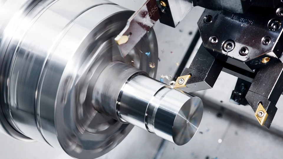
Turning is a subtractive machining process in which a cutting tool removes excess material from a rotating metal part to form a precise outer profile. The rotation of the workpiece creates symmetrical features, while the cutting tool moves linearly to reduce diameter, create grooves, or define thread shapes. This method is commonly executed on lathe machines, which come in both manual and CNC-controlled forms. Key advantages of turning include consistent accuracy, high material removal rates, and compatibility with a wide range of metals and alloys. It is especially suited for shaft-like parts or cylindrical components.
Applications and Turning
Turning plays a vital role in nearly every industry that requires precise, round metal components. In the automotive sector, it’s used to manufacture drive shafts, pistons, hubs, and engine parts that demand tight tolerances and consistent dimensions. Aerospace manufacturers rely on turning operations to produce lightweight yet strong components such as turbine shafts and landing gear elements.
In the medical industry, turning enables the creation of surgical tools, orthopedic implants, and dental components—many of which require ultra-fine finishes and biocompatible materials. Turning is also essential in hydraulic and pneumatic systems, where cylinder bodies, valves, and connector fittings must be perfectly concentric and smooth to ensure leak-free performance.
Beyond these, turning is widely applied in energy, marine, electronics, and heavy machinery industries. Whether for mass production or custom prototyping, turning provides the dimensional accuracy and surface quality needed to meet demanding engineering standards across a wide range of applications.
Straight Turning
Straight turning is one of the most common types of turning operations used to machine external cylindrical surfaces. It is widely applied in both roughing and finishing stages when creating parts with uniform diameters. The following sections explain how straight turning works, its typical use cases, and tips for optimizing performance.
What Is Straight Turning?
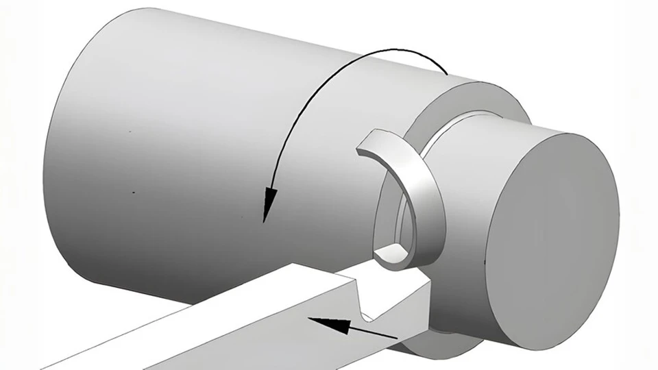
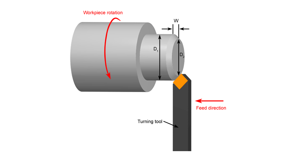
Straight turning involves moving a single-point cutting tool parallel to the axis of a rotating workpiece. As the tool feeds along the surface, it gradually removes material to reduce the diameter and create a smooth, straight cylindrical profile. This is one of the basic types of turning operations performed on a lathe machine and forms the foundation for more complex tasks like taper or contour turning.
Unlike other operations that involve angled or curved tool paths, straight turning uses a linear feed that ensures consistent diameter control and surface finish. It is suitable for both roughing (removing large amounts of material quickly) and finishing (achieving precise size and smoother surface). The operation is most commonly used in conventional lathes, CNC lathes, and Swiss-type machines depending on part requirements.
Common Applications and Workpieces
Straight turning is widely used across industries due to its versatility. In automotive manufacturing, it is applied to produce axles, shafts, hubs, and bearing seats. These components often require tight diameter tolerances and high concentricity. In hydraulic systems, parts like pistons, sleeves, and valve stems are shaped using straight turning to ensure proper sealing and fluid control.
In the aerospace sector, straight turning helps in shaping landing gear rods, actuators, and drive shafts that must be both lightweight and mechanically strong. Medical device manufacturers also use this method for producing orthopedic pins, surgical drill bits, and connector rods with smooth, precise diameters.
Wherever a clean, accurate cylindrical form is required, straight turning is one of the preferred methods. It is a key step in many machining operations, especially when multiple turning types are combined in a single part.
Feed, Depth, and Tool Selection Tips
Choosing the right cutting parameters is critical for successful straight turning. The feed rate—the distance the tool advances per revolution—must balance speed and surface quality. For roughing, higher feed rates are acceptable to remove material faster, but for finishing, slower feeds help achieve smoother surfaces.
Cutting depth should be appropriate for the material hardness and machine rigidity. Shallow cuts reduce the risk of tool deflection and vibration, especially in long, slender parts. For deeper material removal, roughing passes should be followed by light finishing cuts.
Tool selection depends on the material, cutting speed, and desired finish. Carbide-tipped tools are common due to their durability and ability to maintain sharpness at high temperatures. Insert geometry, nose radius, and rake angle all affect the surface finish and chip control. Coolant application can also help with heat management and prolong tool life.
In CNC environments, straight turning is often programmed with G01 (linear interpolation) commands, allowing precise control of feed direction and depth. Proper toolpath planning ensures consistent diameter and avoids dwell marks or steps on the surface.
Taper Turning
Taper turning is used to produce a gradual change in diameter along the length of a cylindrical part, forming a conical surface. It is commonly required in mechanical components like tool holders, connecting shafts, and mold parts where two sections must fit together precisely. Among the different types of turning operations, taper turning is unique in its tool motion and setup complexity. Precision is key, especially when tapers are part of sealing or alignment systems.
Taper Turning Methods
There are several ways to perform taper turning on a lathe machine, each with its own setup style and precision level. The most traditional method is tailstock offset, where the tailstock is shifted laterally to create an angled axis. This approach is simple but less accurate and mostly used on manual lathes for longer tapers.
A more precise technique is the compound rest method, where the tool post is rotated to the required taper angle. This allows the cutting tool to follow a controlled angled path. It’s ideal for short tapers and is commonly used when machining metric or imperial taper threads or socket joints.
For CNC turning, the taper turning by programmed interpolation method is preferred. This involves simultaneous movement of the X and Z axes, producing a controlled taper without manual adjustment. This method is part of advanced types of CNC turning operations and is suitable for high-precision applications in aerospace, automotive, and energy equipment manufacturing.
Each of these taper turning methods can be applied depending on machine capability, taper length, and angle requirements.
Choosing the Right Approach
Selecting the right taper turning method depends on multiple factors, including desired accuracy, taper geometry, and production volume. For quick, non-critical work, the tailstock offset method is sufficient. However, its setup is time-consuming and lacks repeatability, making it less suitable for batch production or fine-tolerance parts.
The compound rest method offers better control and is suitable for single parts or prototype machining. It provides moderate precision and is compatible with both metric and imperial measurements. However, since it requires manual adjustment, it’s not ideal for repeated or automated operations.
For high accuracy and consistent production, especially in industries requiring tight tolerances, the CNC interpolation method is preferred. This technique is highly repeatable and integrates easily into automated production lines. It also eliminates human error in angle setup, making it suitable for precision tapers like Morse tapers or custom-fit mating parts.
When evaluating the different types of turning operations on a lathe machine, taper turning stands out for its importance in applications where alignment and contact surfaces are critical. Choosing the correct method ensures not only dimensional accuracy but also long-term performance of the assembled parts.
Facing
Among the various types of turning operations, facing plays a critical role at the beginning or end of a machining process. It is commonly used to prepare a clean, flat reference surface on the end of a workpiece. This operation directly affects axial alignment and length accuracy, making it essential for components that require precise positioning and smooth assembly. Whether working with cast blanks or pre-machined rods, accurate facing ensures that subsequent processes—such as drilling, turning, or threading—are based on a reliable datum.
Purpose of Facing in Turning
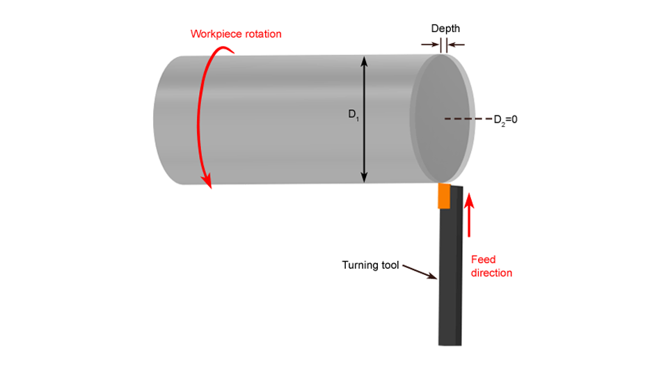
The primary purpose of facing is to machine a surface that is perpendicular to the rotational axis of the lathe. This flat surface is vital for establishing accurate length references and ensuring part symmetry. In industries like aerospace, automotive, and hydraulics, even minor deviations in the end face can lead to functional failures or misalignments. Properly executed facing eliminates irregularities on raw material ends and ensures that follow-up operations maintain their intended dimensions and tolerances.
Toolpaths and Flatness Control
Effective facing requires precise control of tool movement and cutting parameters. Typically, the tool advances radially from the center outward, creating a smooth spiral path. This method helps prevent raised centers or surface ridges. Using the right insert geometry, maintaining proper tool height alignment, and adjusting spindle speed and feed rate all contribute to achieving a flat, high-quality surface. In many types of turning in lathe machines, this operation serves as a foundation for dimensional integrity, so careful attention to setup and execution is essential.
Parting-Off
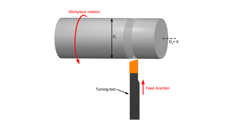
Parting-off is a critical step in turning operations, where the finished component is separated from the raw bar stock. Though it appears simple, this process involves precise control over tool rigidity, cutting depth, and chip evacuation. Poor execution can lead to tool breakage, surface defects, or part deformation. This type of turning is commonly used in mass production of automotive shafts, bushings, and hydraulic fittings. Safe execution and clean separation are essential for both quality and efficiency.
Choosing the Right Cut-Off Tool
The choice of cut-off tool depends heavily on the material type and the diameter of the workpiece. Narrower parting blades reduce cutting force but may deflect more, while wider blades offer better rigidity at the cost of higher resistance. For CNC lathes, insert-type parting tools are often preferred due to their stability and ease of replacement. Selecting an appropriate toolholder shape also ensures better chip flow and tool life. Always align the tool perfectly perpendicular to the spindle axis to minimize deflection and surface irregularities.
Vibration and Workpiece Drop Prevention
Vibration during parting-off can damage the tool or result in poor surface finish. This is especially true for long or thin components. Using a tailstock to support the workpiece or reducing spindle speed during the cut can greatly improve stability. Additionally, minimizing the overhang of the parting tool and ensuring it’s clamped securely helps prevent chattering. To avoid part drop after separation, it’s advisable to use a part catcher or slow down the feed rate near the final cut. These strategies improve safety and part quality in various types of CNC turning operations.
Grooving
Grooving is a specialized turning operation used to create narrow recesses on a workpiece’s surface. These grooves may serve as seats for retaining rings, channels for sealing elements, or simply design-specific features. Unlike straight turning, which removes material along the outer surface, grooving focuses on precise depth and width within a localized area. Due to the narrow tool width and high precision requirement, grooving demands more stable setups and careful parameter control to ensure quality results.
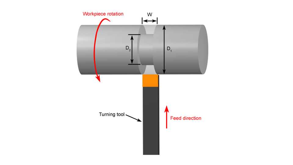
External vs Internal Grooving
External grooving is performed on the outside diameter of cylindrical workpieces. It is typically simpler and allows for easier chip evacuation. Internal grooving, by contrast, is carried out inside a hole or bore, and often requires smaller, more specialized tools. It also poses challenges in visibility and chip clearance. Choosing between internal or external grooving depends entirely on part geometry and function. When selecting tools, factors like shank size, cutting insert profile, and reach depth must align with groove dimensions.
Chip Control and Surface Finish
One of the key difficulties in grooving is managing chip buildup. Poor chip control can lead to surface scratches, heat accumulation, and even tool breakage. Using chip breakers on inserts, applying sufficient coolant, and adjusting feed rates are essential for clean operations. Additionally, maintaining consistent tool paths and minimizing tool deflection helps ensure a smooth groove bottom. For better surface finish, avoid excessive depth in one pass and consider a light finishing cut at reduced speed.
Threading
Threading is one of the most intricate types of turning operations. It involves cutting precise helical grooves on a workpiece’s surface or inside a hole, which enables mechanical fastening and sealing functions. Different types of threading operations exist, including metric, UNC/UNF, pipe threads (NPT/G), and specialized forms for hydraulic or medical parts. Threading requires perfect synchronization between spindle rotation and tool movement to ensure pitch accuracy. Even small errors can lead to failed part assembly or leakage.
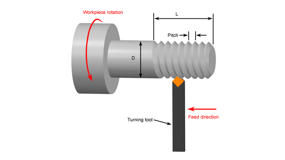
Internal vs External Threading
External threading is typically applied to shafts or bolts, using a tool that moves along the outer surface of a rotating workpiece. Internal threading, on the other hand, creates threads inside bores and requires smaller, more delicate inserts. The main challenges with internal threading include chip evacuation, tool reach, and visibility. Clamping stability and tool overhang control are also more critical for internal threads. While the same types of turning in lathe machine can be used for both operations, setup strategies differ significantly.
Tool Geometry and Pass Planning
The success of threading depends heavily on the geometry of the cutting tool. Factors like thread profile angle (60° for metric and UNC, 55° for BSW), nose radius, and rake angle affect the thread shape and cutting resistance. Additionally, threading is not done in a single pass. Typically, several incremental passes are programmed to reduce cutting load and heat. CNC systems allow precise pitch synchronization, which is essential for complex or deep threads. For beginners exploring different types of turning operations, mastering pass depth and tool angle is key to consistent thread quality.
Drilling
Drilling on a lathe is used to create axial holes in a rotating workpiece. Unlike milling or machining centers, drilling on a lathe involves feeding a stationary drill bit into a spinning part. This method is especially useful for small-diameter pilot holes, deep holes, or when secondary equipment is not available. While drilling is not the primary function of a lathe, it is an essential part of many turning operations that require internal features.
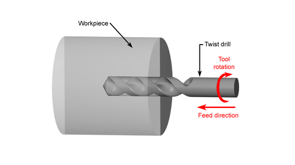
Tailstock vs Turret Drilling
Drilling can be performed using the tailstock or the turret, depending on the type of lathe. On conventional lathes, the tailstock is commonly used for supporting drill bits. It offers strong axial alignment but requires manual setup and limited adjustability. In contrast, CNC lathes often employ turret-mounted drills. These tools are programmable and can switch automatically, improving cycle time and repeatability. However, turret drilling systems require precise tool alignment to avoid runout or taper errors.
Preventing Hole Drift and Burnout
Hole deviation and tool damage are two common issues in lathe drilling. To prevent drift, the workpiece surface must be centered and flat before drilling starts. Spot drills or center drills are often used to guide the main drill bit accurately. Using cutting fluids is crucial to minimize heat buildup and tool wear—especially for deep holes. Peck drilling cycles can help eject chips efficiently and reduce friction. Avoiding excessive feed rates and dull drill bits is also key to maintaining hole integrity and tool life.
Boring
Boring is a machining operation used to enlarge and finish holes that have already been drilled or reamed. This process is essential for enhancing hole diameter accuracy, improving surface finish, and achieving tighter concentricity. In many complex parts, boring is performed after drilling as part of the overall types of turning operations sequence, especially when holes require precise dimensional control or alignment for shafts, seals, or bearings.
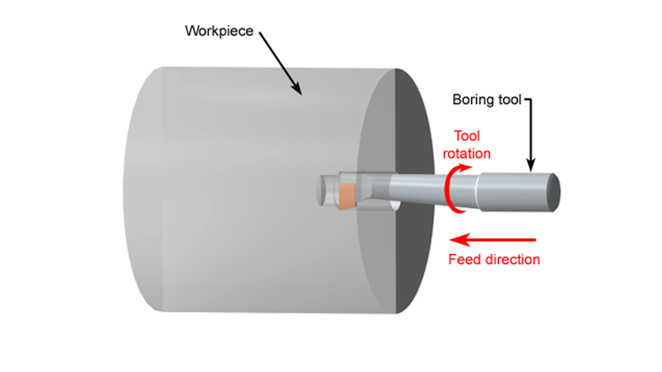
Rough vs Finish Boring
Rough boring is the first stage, designed to remove the bulk of material quickly and prepare the hole close to the target dimension. It uses larger depth of cut at moderate speeds and is prone to generating some tool marks. Finish boring follows with light cuts and slower feed rates to improve surface quality and achieve tight tolerances. This two-step approach is standard practice in types of turning operations to balance efficiency and precision. Using the right tools and planning separate passes prevents tool overload and ensures a better final surface.
Micrometric Adjustments and Runout Control
Achieving geometric accuracy in boring demands precise micrometric tool adjustments. Adjusting the boring bar by micrometers allows small diameter changes without removing the setup. Controlling runout—ensuring the tool stays centered—is crucial for maintaining concentricity. This involves checking the boring bar alignment with a test bar or dial indicator before cutting. Additionally, minimizing bar overhang reduces vibration and prevents “chatter” marks inside the hole. These practices are part of advanced types of turning in lathe machine workflows and ensure reliable, high-precision results.
Knurling
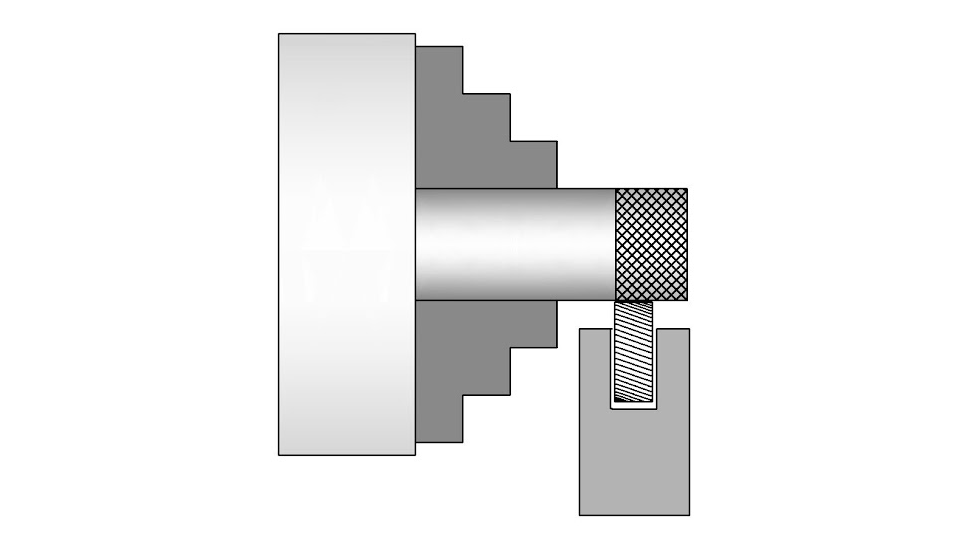
Knurling is a specialized turning process used to create patterned textures on cylindrical surfaces, primarily for improving grip. This type of turning operation is especially common on tool handles, knobs, and mechanical grips where secure handling is critical. While it does not involve material removal like other types of turning operations, it deforms the surface using pressure. Precision in knurling setup is essential, as poorly aligned tools or incorrect pressure can cause overlapping patterns or surface damage.
Knurl Types and Patterns
There are three main knurling patterns: straight, diagonal, and diamond. Straight knurling produces parallel lines and is commonly used for aesthetic or light-grip applications. Diagonal knurling, with its angled pattern, offers stronger grip and is suitable for rotating knobs or components. Diamond knurling, a combination of intersecting diagonal lines, provides the best anti-slip performance and is ideal for hand tools. Choosing the correct knurl type depends on both functional and visual design requirements of the part.
Process Settings and Avoiding Defects
Proper knurling requires attention to pressure, speed, and synchronization. Use slow spindle speeds and apply firm, consistent pressure to avoid partial patterns or double-tracking. Align the knurling tool center with the workpiece axis, and ensure even feed to prevent jumping or irregular pitch. Always verify tool sharpness and check the compatibility between the knurl tool pitch and workpiece diameter. A poorly chosen knurl pitch can lead to distorted patterns or surface tearing.
Polygon Turning
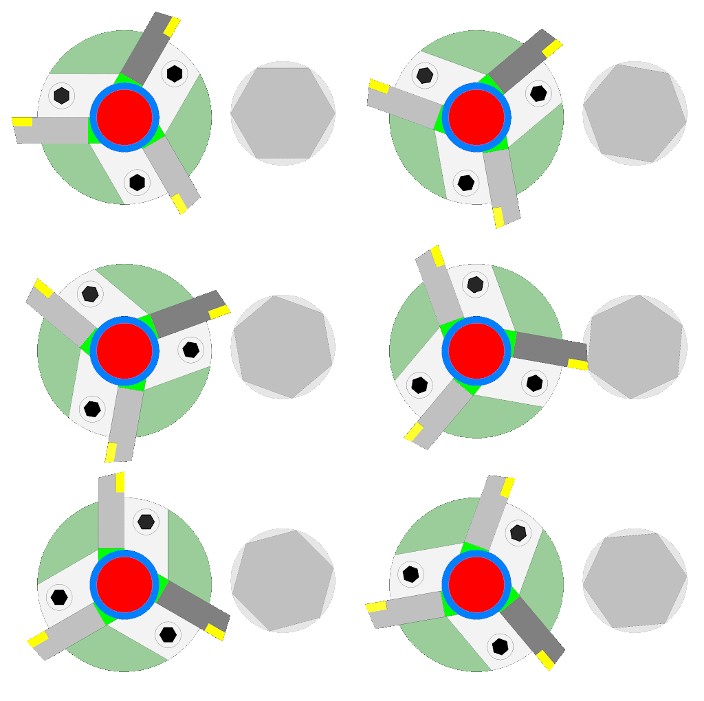
Polygon turning is a specialized form of machining that enables the creation of non-circular profiles, such as hexagons and squares, on rotating workpieces. Unlike traditional turning, which produces round shapes, polygon turning relies on a synchronized motion between the rotating workpiece and a polygon turning cutter. This technique falls under the broader types of turning operations and requires high precision, especially in applications where flat surfaces must align perfectly on a cylindrical base.
Machines and Setup Requirements
To implement polygon turning, special tooling and setup are essential. Most operations require polygon turning attachments or machines equipped with synchronous drive systems. These systems ensure the cutter’s motion is perfectly timed with the spindle rotation, enabling the formation of exact-sided shapes without stopping the workpiece rotation. The synchronization eliminates the need for indexing or secondary milling steps, significantly improving production efficiency.
Applications in Valve and Connector Components
Polygon turning finds frequent use in components that demand flat engagement faces, such as pneumatic valve cores, hydraulic couplings, and connector fittings. These parts often require high torque transmission or anti-slip engagement, making multi-sided profiles ideal. Among all types of turning operations, polygon turning stands out due to its capability to shape complex forms directly on a lathe without repositioning.
Maintaining tool rigidity, ensuring sharp cutter edges, and confirming precise machine timing are crucial to achieving dimensional accuracy in polygon turning. Because of the tight tolerances and specific geometric requirements, this process is typically found in high-value part production, such as aerospace fittings, automotive connectors, and custom mechanical locks.
Eccentric Turning
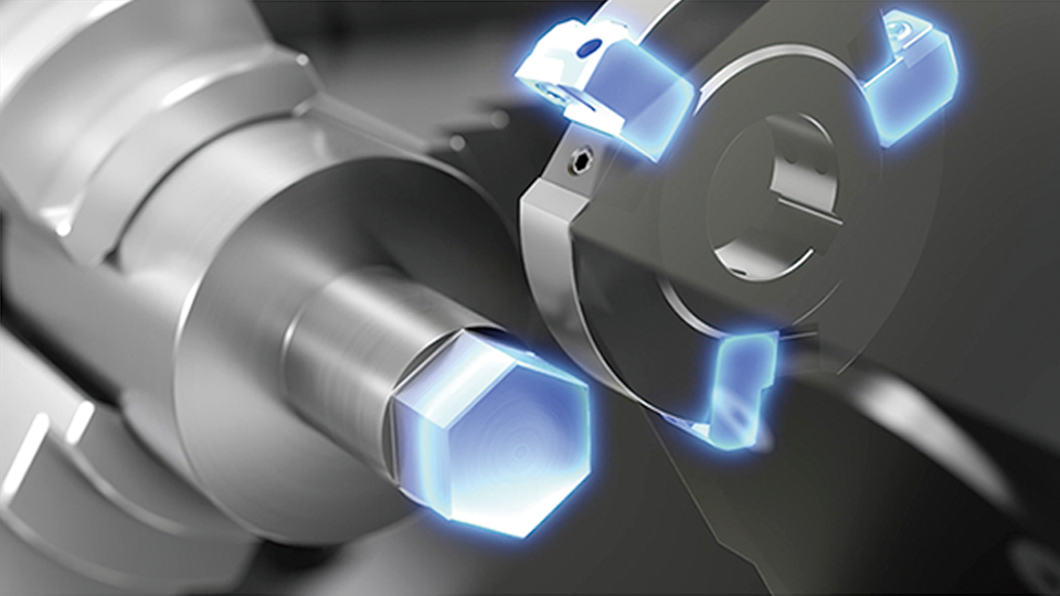
Eccentric turning is a specialized form of lathe operation where the machined surfaces do not share a common centerline with the main axis of the workpiece. This technique is essential for producing parts with offset or multiple centers, such as camshafts, eccentric wheels, or pump components. Among the various types of turning operations, eccentric turning is one of the most challenging due to its need for precise positioning and balance during rotation.
Off-Center Clamping Techniques
To execute eccentric turning accurately, it is critical to set the workpiece off-center relative to the lathe spindle. This is usually achieved using special offset chucks, step fixtures, or custom eccentric collets. The machine’s coordinate system must be adjusted accordingly to reflect the new rotational axis. This step requires careful measurement and verification to ensure that the cutting path aligns with the eccentric geometry specified in the part drawing. Mistakes in this stage may lead to dimensional inaccuracy or tool crashes.
Balancing and Safety Concerns
Because the mass is distributed unevenly around the spinning axis, unbalanced forces can generate excessive vibration. These vibrations not only reduce machining accuracy but can also damage the machine spindle or lead to tool breakage. To mitigate this, counterweights are sometimes added to balance the load, and cutting speeds must be kept lower than in symmetric turning operations. Operators should also ensure that clamping is secure and avoid standing in the radial path of rotating parts.
Conclusion
With so many types of turning operations available, mastering their differences is key to improving machining efficiency and part quality. From basic straight turning to complex eccentric and polygon turning, each method serves a unique role in shaping, separating, or refining parts. Selecting the right process depends not only on geometry and material but also on your production goals and technical constraints. Understanding how and when to apply each technique can significantly reduce waste, improve tolerances, and boost overall productivity.
For manufacturers seeking reliable implementation of these operations, the right machine tools make all the difference. Whether it’s high-precision boring or large-diameter facing, machines must support both repeatability and versatility. That’s why modern workshops and global OEMs increasingly turn to trusted suppliers like Rosnok, whose CNC lathe solutions are designed to handle diverse turning needs with precision, power, and intelligent automation. Rosnok’s machines don’t just execute turning—they optimize it, empowering manufacturers to meet complex demands with confidence and build a foundation for long-term precision and productivity.
